1. Introduction
Thank you for choosing the CREWORKS 750W Mini Metal Lathe. This manual provides essential information for the safe and efficient operation, maintenance, and troubleshooting of your new machine. Please read this manual thoroughly before operating the lathe to ensure proper use and to prevent injury or damage.
This mini metal lathe is designed for precision machining tasks, including turning, drilling, threading, and cutting various materials such as metal, plastic, and wood. Its robust construction and precise controls make it suitable for both hobbyists and professionals.
2. Safety Instructions
Operating any machinery carries inherent risks. Adhere to the following safety guidelines to minimize potential hazards:
- Always wear appropriate personal protective equipment (PPE), including safety glasses, hearing protection, and sturdy footwear. Avoid loose clothing, jewelry, and long hair that could get caught in moving parts.
- Ensure the work area is clean, well-lit, and free from obstructions. Keep children and unauthorized personnel away from the machine.
- Before making any adjustments or maintenance, always disconnect the lathe from the power supply.
- Never leave the machine unattended while it is running.
- Use only sharp, correctly ground cutting tools. Dull tools can cause excessive force and lead to accidents.
- Secure workpieces firmly in the chuck or collet. Loose workpieces can become dangerous projectiles.
- Do not attempt to stop the chuck or workpiece with your hand. Allow the machine to come to a complete stop naturally.
- Always use the chuck guard when operating the lathe to protect against chips and debris.
- Familiarize yourself with the emergency stop button location and function.
- Do not operate the lathe under the influence of drugs, alcohol, or medication that may impair judgment.
3. Product Overview
The CREWORKS 750W Mini Metal Lathe is a compact yet powerful machine designed for precision metalworking. It features a robust cast iron construction for stability and durability.

Figure 3.1: General view of the CREWORKS 750W Mini Metal Lathe.
Key Features:
- Powerful 750W Motor: Provides ample power for various metalworking tasks.
- Variable Speed Control: Spindle speed adjustable from 0 to 2500 RPM with a real-time digital display for precise monitoring.
- High Precision 3-Jaw Chuck: A 125mm chuck designed for securely holding both square and round workpieces.
- Robust Construction: Durable cast iron frame ensures long life and superior corrosion resistance.
- Safety Features: Includes a transparent chuck guard to protect the operator from chips and debris.
- Wide Application: Capable of turning, drilling, threading, and cutting various materials including metal, plastic, and wood.

Figure 3.2: Transparent chuck guard for enhanced safety.
4. Specifications
The following table outlines the technical specifications for the CREWORKS 750W Mini Metal Lathe:
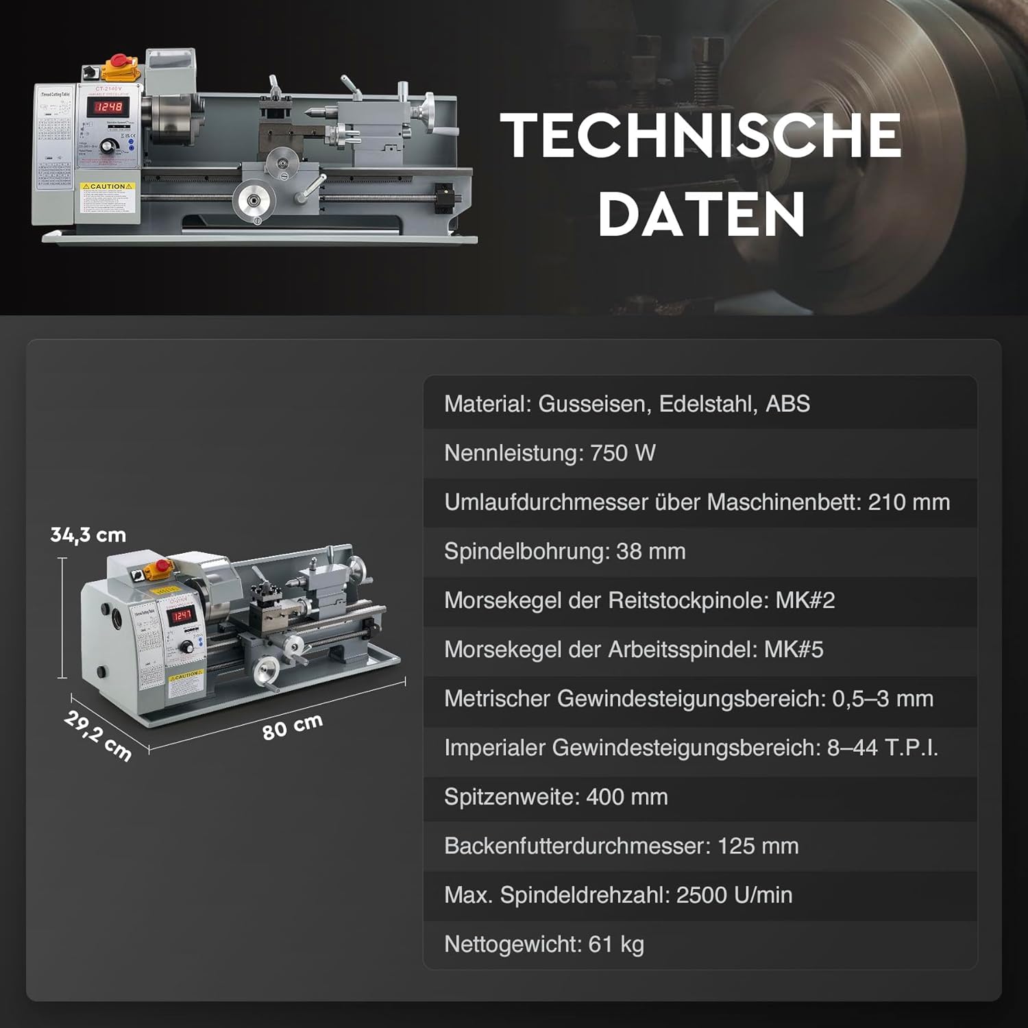
Figure 4.1: Technical data and dimensions overview.
| Parameter | Value |
|---|---|
| Material | Cast iron, Stainless steel, ABS |
| Rated Power | 750 W |
| Swing Over Bed | 210 mm |
| Distance Between Centers | 400 mm |
| Spindle Bore | 38 mm |
| Spindle Taper | MK#5 |
| Tailstock Taper | MK#2 |
| Chuck Diameter | 125 mm |
| Max. Spindle Speed | 2500 rpm |
| Metric Thread Pitch Range | 0.5–3 mm |
| Imperial Thread Pitch Range | 8–44 T.P.I. |
| Net Weight | 61 kg |
5. Setup
5.1 Unpacking and Inspection
- Carefully remove the lathe from its packaging. Retain all packaging materials for future transport or storage.
- Inspect the machine for any signs of shipping damage. Report any damage to the carrier and seller immediately.
- Clean all protective coatings (e.g., grease, oil) from the machine surfaces using a suitable degreaser.
- Verify that all components and accessories listed in the packing list are present.
5.2 Mounting and Leveling
- Place the lathe on a sturdy, level workbench capable of supporting its weight (61 kg).
- Secure the lathe to the workbench using appropriate bolts and nuts to prevent movement during operation.
- Use a precision level to ensure the lathe bed is perfectly level. Adjust the mounting points as necessary. Proper leveling is crucial for accurate machining.
5.3 Electrical Connection
- Ensure the power supply matches the voltage and frequency requirements specified on the machine's nameplate.
- Connect the lathe to a grounded electrical outlet. Do not use extension cords unless absolutely necessary, and ensure they are rated for the machine's power requirements.
- Before powering on, ensure the emergency stop button is disengaged and all controls are in the OFF position.
6. Operation
6.1 Powering On and Speed Control
- After ensuring all safety checks are complete, connect the lathe to power.
- Press the main power switch to turn on the machine. The digital display should illuminate.
- Use the speed control knob to adjust the spindle RPM. The digital display will show the current speed in real-time.

Figure 6.1: Digital display for precise RPM control.
6.2 Workpiece Mounting (3-Jaw Chuck)
- Ensure the lathe is powered off and the chuck is stationary.
- Insert the chuck key into the chuck and rotate it to open the jaws sufficiently for your workpiece.
- Insert the workpiece into the chuck, ensuring it is seated firmly and centered.
- Tighten the chuck jaws evenly using the chuck key. Remove the chuck key immediately after tightening.

Figure 6.2: 3-Jaw chuck clamping ranges.
6.3 Tool Post and Tooling
- Mount the appropriate cutting tool in the 4-way tool post.
- Adjust the tool height so that the cutting edge is precisely on the centerline of the workpiece.
- Securely tighten the tool post screws to prevent tool movement during cutting.
6.4 Basic Turning Operations
The lathe features precision handwheels for controlling the bed slide, cross slide, compound rest, and tailstock feed. These allow for precise manual control during machining operations.

Figure 6.3: Handwheels for precise control of lathe movements.
- Longitudinal Turning: Use the bed slide handwheel for feeding the tool along the length of the workpiece.
- Facing: Use the cross slide handwheel to feed the tool across the face of the workpiece.
- Taper Turning: Adjust the compound rest angle for turning tapers.
- Threading: Refer to the threading chart (if provided on the machine) for appropriate gear settings and feed rates.
The double V-shaped guide rails ensure smooth and precise movement of the carriage and tailstock, contributing to high machining accuracy.
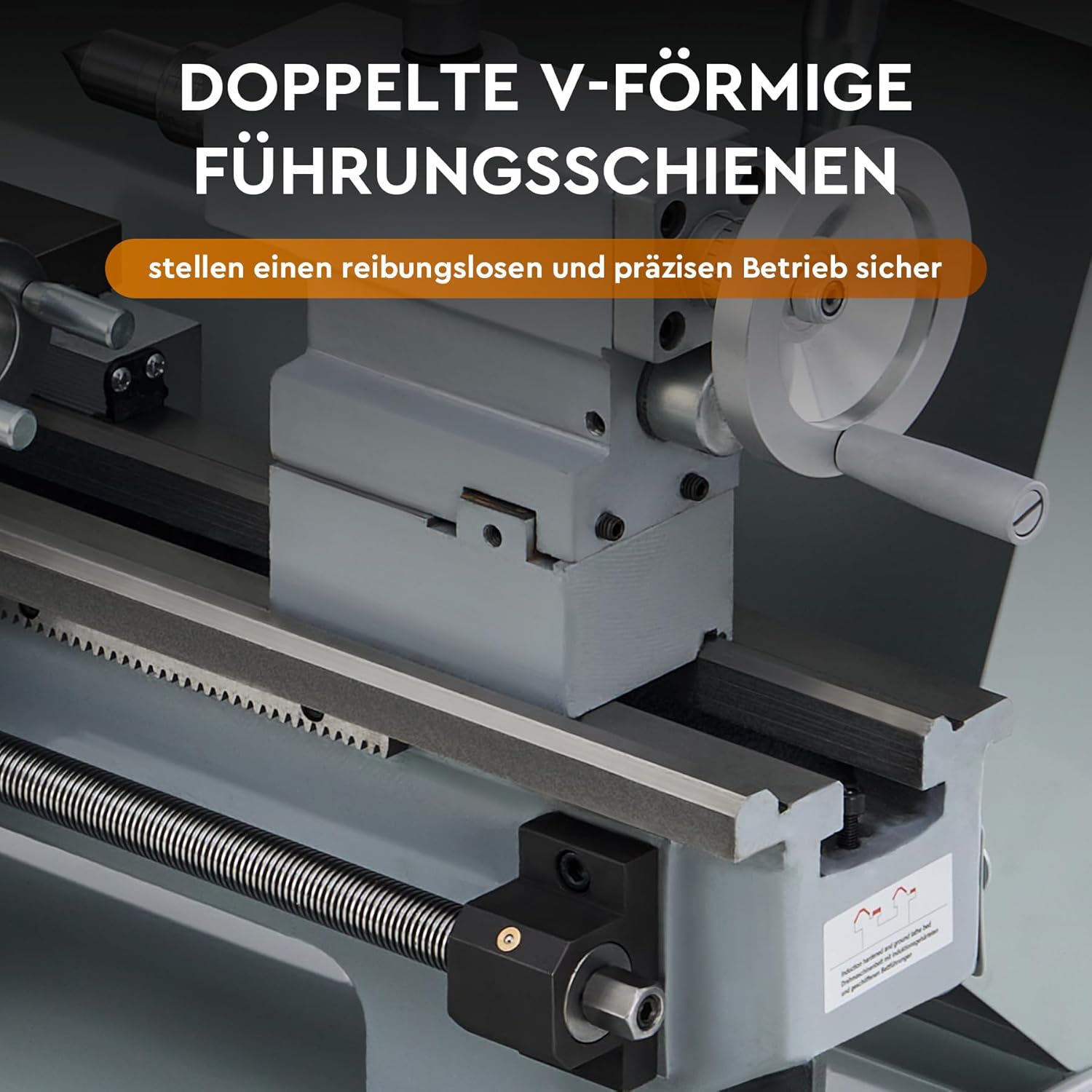
Figure 6.4: Double V-shaped guide rails for smooth operation.
7. Maintenance
Regular maintenance is crucial for the longevity and performance of your lathe. Always disconnect power before performing any maintenance.
7.1 Cleaning
- After each use, clean all chips and debris from the lathe bed, carriage, and other surfaces. Use a brush or shop vacuum; never use compressed air as it can embed chips into moving parts.
- Wipe down all exposed metal surfaces with a clean cloth to prevent rust.
7.2 Lubrication
- Regularly lubricate all moving parts, including the lead screw, cross slide, compound rest, and tailstock quill. Refer to the lubrication points indicated in the machine's diagrams.
- Use high-quality machine oil suitable for lathes.
7.3 Adjustments
- Periodically check and adjust the gibs on the carriage, cross slide, and compound rest to eliminate excessive play.
- Inspect the drive belts for wear and proper tension. Adjust or replace as needed. The lathe features a durable metal gear set for power transmission.

Figure 7.1: Internal view of the lathe's gearbox showing the metal gears.
8. Troubleshooting
This section provides solutions to common issues you might encounter. For problems not listed here, contact customer support.
| Problem | Possible Cause | Solution |
|---|---|---|
| Lathe does not power on | No power supply; Emergency stop engaged; Faulty switch | Check power connection; Disengage emergency stop; Inspect power switch/fuse |
| Spindle does not rotate | Motor issue; Belt slipped/broken; Speed control set to zero | Check motor connection; Inspect/adjust/replace belt; Increase speed setting |
| Excessive vibration/noise | Unbalanced workpiece; Loose mounting; Dull cutting tool; Worn bearings | Balance workpiece; Tighten mounting bolts; Sharpen/replace tool; Inspect bearings |
| Inaccurate cuts | Lathe not level; Loose gibs; Worn lead screw; Improper tool setup | Level the lathe; Adjust gibs; Inspect lead screw; Verify tool height and sharpness |
9. Warranty and Support
For warranty information, please refer to the documentation provided at the time of purchase or contact your retailer. CREWORKS is committed to providing quality products and support.
If you require technical assistance, spare parts, or have any questions regarding the operation or maintenance of your CREWORKS Mini Metal Lathe, please contact the seller or CREWORKS customer service. Please have your model number (210x400mm) and purchase date available when contacting support.