1. Introduction
Thank you for choosing the CREWORKS 1100W Mini Metal Lathe. This manual provides essential information for the safe and efficient operation, maintenance, and troubleshooting of your new machine. Please read this manual thoroughly before operating the lathe to ensure proper use and to prevent injury or damage.
This powerful mini metal lathe, measuring 110 x 43 cm, is equipped with an 1100 W motor, making it suitable for small to medium-sized metalworking projects. It features a 220 mm swing over the bed, a 750 mm distance between centers, and a 38 mm spindle bore.

Figure 1: Overview of the CREWORKS Mini Metal Lathe, highlighting its compact design and key operational areas.
2. Safety Instructions
Operating any machinery carries inherent risks. Adhere to all safety precautions to prevent accidents and ensure personal safety.
2.1 General Safety
- Always wear appropriate personal protective equipment (PPE), including safety glasses, hearing protection, and sturdy footwear.
- Do not wear loose clothing, gloves, jewelry, or long hair that could become entangled in moving parts.
- Ensure the work area is clean, well-lit, and free from obstructions.
- Keep children and unauthorized personnel away from the machine.
- Never operate the lathe under the influence of drugs, alcohol, or medication that impairs judgment.
2.2 Electrical Safety
- Ensure the power supply matches the machine's requirements (220V AC).
- Always disconnect power before performing maintenance, adjustments, or when changing accessories.
- Do not operate the machine with damaged cords or plugs.
2.3 Operation Safety
- Secure the workpiece firmly in the chuck or between centers.
- Use sharp, correctly ground cutting tools.
- Never leave the machine unattended while it is running.
- Always use the chuck guard to protect against chips and broken tools.
- Do not attempt to stop the chuck or workpiece with your hand.
- Clear chips and debris only after the machine has come to a complete stop.
3. Setup and Installation
3.1 Unpacking and Inspection
Carefully remove the lathe from its packaging. Inspect all components for any signs of shipping damage. Report any damage immediately to the carrier and supplier. Ensure all accessories listed in the packing list are present.
3.2 Placement and Mounting
The lathe should be placed on a sturdy, level workbench capable of supporting its weight (approximately 75 kg). Secure the lathe to the workbench using appropriate fasteners to prevent movement during operation.
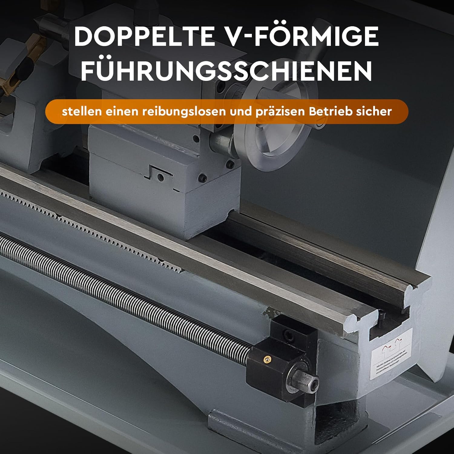
Figure 2: Double V-shaped guide rails ensure smooth and precise movement of the carriage and tailstock.
3.3 Electrical Connection
Connect the lathe to a grounded 220V AC power outlet. Ensure the circuit can handle the 1100W power requirement of the machine. Avoid using extension cords if possible; if necessary, use a heavy-duty, grounded extension cord rated for the lathe's power.
4. Operating Instructions
4.1 Controls and Features
The lathe offers complete control over its operations. The rotation speed can be adjusted from 0 to 3000 rpm and is monitored via a real-time digital display. The machine features well-designed headstocks and tailstocks, a large through-hole, and a 4-way tool post for versatile work.

Figure 3: Granular precision controls including digital RPM display, handwheels for bed slide, cross slide, compound rest, and tailstock feed.

Figure 4: Digital display for stepless speed adjustment up to 3000 RPM.
4.2 Workpiece Mounting
The 12.5 cm high-precision three-jaw chuck is designed to securely hold both square and round workpieces. Ensure the workpiece is centered and clamped tightly before starting any operation.

Figure 5: Adaptable 3-jaw chuck with clamping ranges for internal (2.5-125 mm) and external (38-110 mm) jaws.
4.3 Basic Operations
This mini metal lathe is designed for precision tasks such as turning, drilling, threading, and cutting across various materials including wood, plastic, brass, and aluminum.
- Turning: Adjust the cutting tool to the desired depth and feed rate. Engage the automatic feed or use the handwheels for manual control.
- Drilling: Mount a drill chuck in the tailstock. Advance the drill bit into the workpiece using the tailstock handwheel.
- Threading: Refer to the threading chart on the machine for appropriate gear settings. Ensure the correct tool is installed and the feed rate is set for the desired thread pitch.

Figure 6: Wide range of applications including metalworking, drilling, internal/external threading, polishing, and woodworking.
5. Maintenance
Regular maintenance ensures the longevity and optimal performance of your CREWORKS Mini Metal Lathe.
5.1 Cleaning
- After each use, clean the lathe thoroughly, removing all chips and debris from the bed, carriage, and chuck.
- Use a brush or air hose for cleaning. Avoid using bare hands to remove sharp chips.
- Wipe down all exposed metal surfaces with a lightly oiled cloth to prevent rust.
5.2 Lubrication
- Regularly lubricate the lead screw, cross slide, compound rest, and tailstock quill with machine oil.
- Check and replenish the gearbox oil as per the maintenance schedule.
5.3 Gear Maintenance
The lathe features a durable metal gear set designed for wear-resistant construction and efficient power transmission. Periodically inspect the gears for wear or damage. Replace any worn gears promptly to maintain precision and prevent further damage.
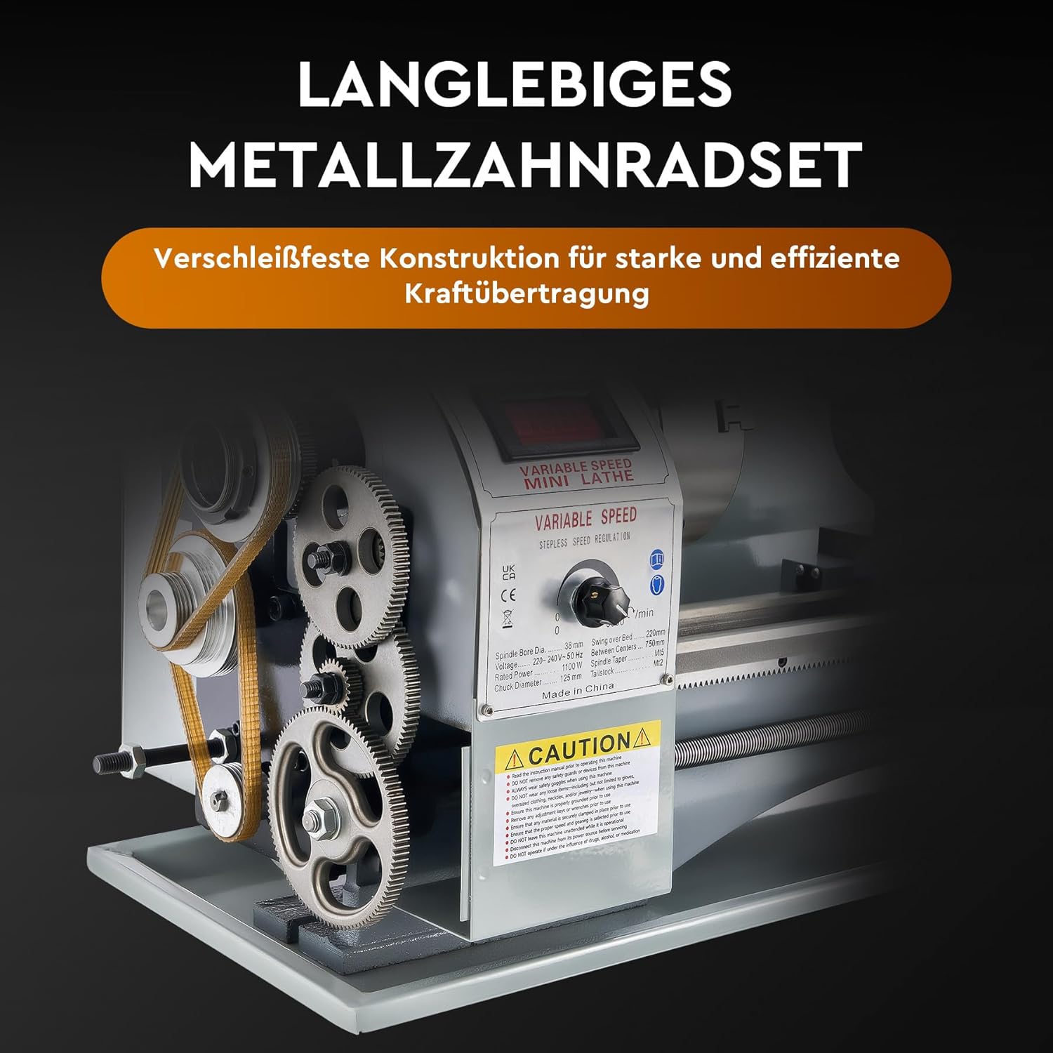
Figure 7: Durable metal gear set for strong and efficient power transmission.
6. Troubleshooting
This section addresses common issues you might encounter during the operation of your lathe.
| Problem | Possible Cause | Solution |
|---|---|---|
| Lathe does not start | No power supply; Emergency stop engaged; Motor overload. | Check power connection; Release emergency stop button; Allow motor to cool down. |
| Excessive vibration | Unbalanced workpiece; Loose mounting; Worn bearings. | Balance workpiece; Tighten mounting bolts; Inspect and replace bearings if necessary. |
| Poor surface finish | Dull or incorrect cutting tool; Incorrect speed/feed rate; Workpiece not rigid. | Sharpen or replace tool; Adjust speed/feed; Ensure workpiece is securely mounted. |
| Spindle speed inconsistent | Motor issues; Control board malfunction. | Contact customer support for motor or control board inspection. |
7. Specifications
The following table details the technical specifications for the CREWORKS 1100W Mini Metal Lathe (Model MLM).

Figure 8: Technical specifications of the lathe.
| Feature | Specification |
|---|---|
| Model Number | MLM |
| Material | Metal (Cast Iron) |
| Rated Power | 1100 W |
| Horsepower | 1.5 HP |
| Swing Over Bed | 220 mm (8.7 inches) |
| Distance Between Centers | 750 mm (29.5 inches) |
| Spindle Bore | 38 mm |
| Tailstock Taper | MK#2 |
| Headstock Taper | MK#5 |
| Metric Thread Pitch Range | 0.5-2.5 mm |
| Imperial Thread Pitch Range | 10-44 T.P.I. |
| Chuck Diameter | 125 mm |
| Max. Spindle Speed | 3000 RPM |
| Product Dimensions (L x W x H) | 110 x 43 x 34.5 cm (approx.) |
| Net Weight | 75 kg |
| Power Source | AC |
8. Customer Support
For technical assistance, spare parts, or warranty inquiries, please contact CREWORKS customer service. Refer to your purchase documentation for specific contact details.