1. Product Overview
The OONO D-1437 is a 2-channel power distribution module featuring rocker switch thermal circuit breaker overload protectors. Designed for DIN rail mounting, this module provides protection against overcurrent conditions for electrical circuits. Each channel includes a 10A thermal circuit breaker, allowing manual control of the output state (RESET or OFF) and indicating normal operation with a built-in red light.
2. Key Features
- Input Voltage: AC 125V to 250V, 50-60Hz.
- Maximum Total Input Current: 20A (per position terminal block).
- Maximum Output Current: 10A per channel.
- Maximum Total Output Current: 20A.
- Circuit Breakers: Two 10A rocker switch thermal circuit breaker overload protectors.
- Switch Functionality: Manual RESET or OFF states with integrated red indicator light for normal output.
- Terminal Blocks: Pitch 7.62mm (0.3 inch), suitable for 26AWG to 10AWG (4.0mm square) wires.
- DIN Rail Mount: High-quality fireproof nylon material carrier, compatible with 35mm, 32mm, and 15mm DIN rails.
- Construction: FR-4 fiberglass dual copper layers PCB.
3. Technical Specifications
| Specification | Value |
|---|---|
| Brand | OONO |
| Model | D-1437 |
| Input Voltage | AC 125-250V, 50/60Hz |
| Max Total Input Current | 20A |
| Max Output Current (per channel) | 10A |
| Max Total Output Current | 20A |
| Circuit Breaker Type | Thermal, Rocker Switch |
| Number of Poles | 2 |
| Mounting Type | DIN Rail Mount |
| Terminal Block Pitch | 7.62mm (0.3 inch) |
| Wire Range | 26AWG to 10AWG (4.0mm²) |
| Strip Length | 8mm |
| Screw Material | M3, Steel, Cr3+ Zn plated |
| Pin Header and Cage Material | Brass |
| PCB Material | FR-4 fiberglass dual copper layers |
4. Safety Information
WARNING: Electrical shock hazard. Installation and servicing should only be performed by qualified personnel. Always disconnect power at the main circuit breaker or fuse box before installing or servicing this device.
- Ensure all wiring complies with local and national electrical codes.
- Do not exceed the specified voltage and current ratings of the device.
- Verify proper wire gauge for the current load to prevent overheating.
- Ensure secure connections at all terminal blocks to prevent loose contacts and potential hazards.
- This device is designed for indoor use in dry environments. Avoid exposure to moisture or extreme temperatures.
5. Setup and Installation
5.1 DIN Rail Mounting
The OONO D-1437 module is designed for easy installation on standard DIN rails (35mm, 32mm, or 15mm width). To mount, align the module's clips with the DIN rail and press firmly until it snaps into place. To remove, gently pull the release mechanism (if present) or pry the module off the rail.
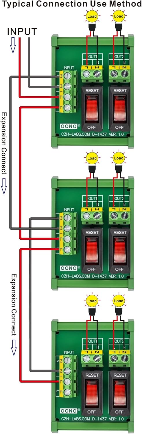
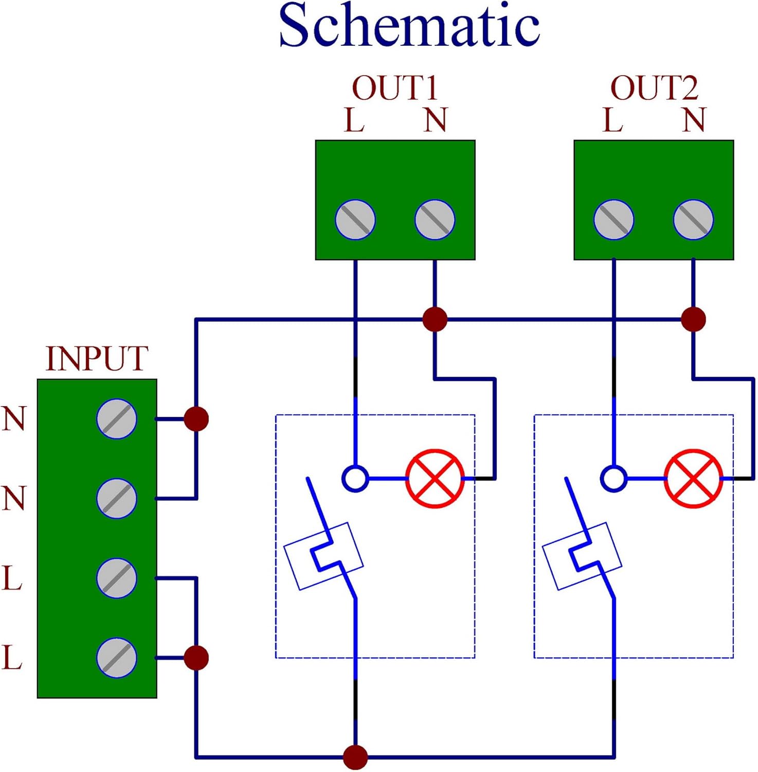
5.2 Wiring Connections
Refer to the schematic and connection diagrams for proper wiring. Ensure power is disconnected before making any connections.
- Input Terminals: Connect the AC 125-250V power supply to the input terminals labeled 'N' (Neutral) and 'L' (Line). The module supports a maximum total input current of 20A.
- Output Terminals: Each channel has 'L' and 'N' output terminals. Connect your load to the corresponding output channel. Each channel supports a maximum output current of 10A. The maximum total output current for the module is 20A.
- Wire Specifications: Use wires within the range of 26AWG to 10AWG (4.0mm²). Strip wire insulation approximately 8mm before inserting into the terminal blocks. Tighten M3 screws securely.


5.3 Dimensions
For precise integration into your electrical panel, refer to the detailed dimensional drawing below.

5.4 Installation Overview Video
Watch this video for a visual guide on the product's features and installation process.
6. Operating Instructions
The OONO D-1437 features two independent rocker switches, each controlling one output channel.
- ON/RESET Position: When the rocker switch is pressed to the 'RESET' side, the circuit breaker is closed, allowing power to flow to the connected load. A built-in red indicator light will illuminate when the output is normal.
- OFF Position: When the rocker switch is pressed to the 'OFF' side, the circuit breaker is open, disconnecting power to the connected load. The red indicator light will be off.
- Overload Protection: In the event of an overcurrent, the thermal circuit breaker will automatically trip, moving the rocker switch to the 'OFF' position and disconnecting the load to prevent damage. To reset after an overload, allow a brief cooling period, then manually press the switch to the 'RESET' position. If the breaker trips repeatedly, investigate the cause of the overload.
7. Maintenance
The OONO D-1437 is designed for minimal maintenance. However, periodic inspection is recommended to ensure optimal performance and safety.
- Cleaning: Ensure the module is free from dust and debris. Use a dry, soft cloth for cleaning. Do not use liquid cleaners or solvents.
- Connection Check: Periodically inspect all wire connections to ensure they remain tight and secure. Loose connections can lead to overheating or intermittent operation.
- Visual Inspection: Check for any signs of physical damage, discoloration, or burning on the module or wiring. Replace the unit immediately if any damage is observed.
8. Troubleshooting
- No Power to Load:
- Check if the rocker switch is in the 'RESET' position.
- Verify that the input power supply is active.
- Inspect all wiring connections for looseness or damage.
- Circuit Breaker Trips Repeatedly:
- This indicates an overcurrent condition. Disconnect the load and check for short circuits or excessive current draw.
- Ensure the connected load does not exceed the 10A rating of the individual channel or the 20A total rating of the module.
- Allow the breaker to cool down before attempting to reset.
- Indicator Light Not On:
- The indicator light illuminates when the output is normal and the switch is in the 'RESET' position. If it's off, check the switch position, input power, and load connection.
- If the breaker has tripped, the light will be off.
9. Warranty and Support
For warranty information and technical support, please refer to the documentation provided at the time of purchase or contact the manufacturer directly. Keep your purchase receipt as proof of purchase.