1. Introduction
This manual provides essential information for the safe and efficient operation, setup, and maintenance of your CREWORKS 220x750mm 1100W Metal Lathe. Please read this manual thoroughly before operating the machine to ensure proper use and to prevent injury or damage.
The CREWORKS Metal Lathe is designed for precision metalworking tasks, including turning, drilling, threading, and cutting. Its robust construction and digital display for speed adjustment offer enhanced control and accuracy for various applications.
2. Safety Instructions
WARNING: Failure to follow these safety instructions may result in serious injury or death.
- Always wear appropriate personal protective equipment (PPE), including safety glasses, hearing protection, and suitable clothing. Avoid loose clothing, jewelry, and long hair.
- Ensure the work area is clean, well-lit, and free from obstructions.
- Never operate the lathe under the influence of drugs, alcohol, or medication that impairs judgment.
- Before making any adjustments or maintenance, always disconnect the machine from the power supply.
- Securely clamp all workpieces in the chuck or collet before starting the machine.
- Do not leave the machine unattended while it is running.
- Keep hands and fingers away from moving parts, especially the chuck and cutting tools.
- Use only sharp, correctly ground cutting tools. Dull tools can cause kickback and damage.
- Ensure all guards and safety devices are in place and functioning correctly before operation.
- Familiarize yourself with the emergency stop button location and operation.
3. Product Overview
The CREWORKS Metal Lathe is engineered for precision and durability. Key components and features are detailed below.
3.1 Main Components

- Headstock: Houses the main spindle, chuck, and gear train for speed control.
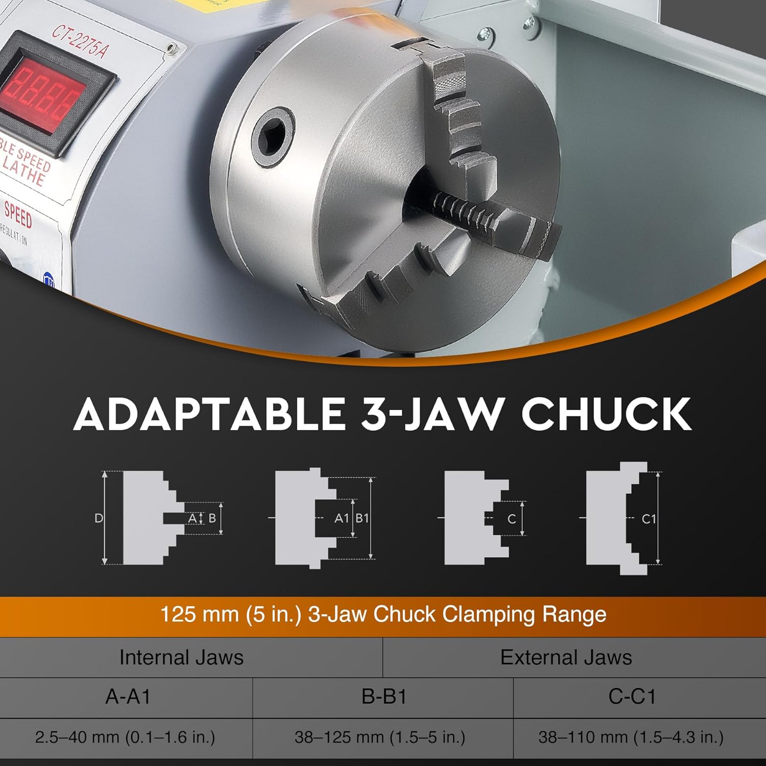
- Chuck: A 3-jaw self-centering chuck for holding workpieces.
- Tool Post: Holds the cutting tools. Adjustable for various operations.
- Carriage: Moves along the bed, carrying the cross slide and tool post.
- Cross Slide: Allows the tool to move perpendicular to the workpiece.
- Compound Rest: Provides angular adjustment for the cutting tool.
- Tailstock: Supports the end of long workpieces or holds drilling/reaming tools.
- Bed: The main frame of the lathe, providing precision guide rails for the carriage and tailstock.
- Lead Screw: Used for automatic feeding and thread cutting.
- Control Panel: Features power switches, speed adjustment, and digital display.
3.2 Key Features
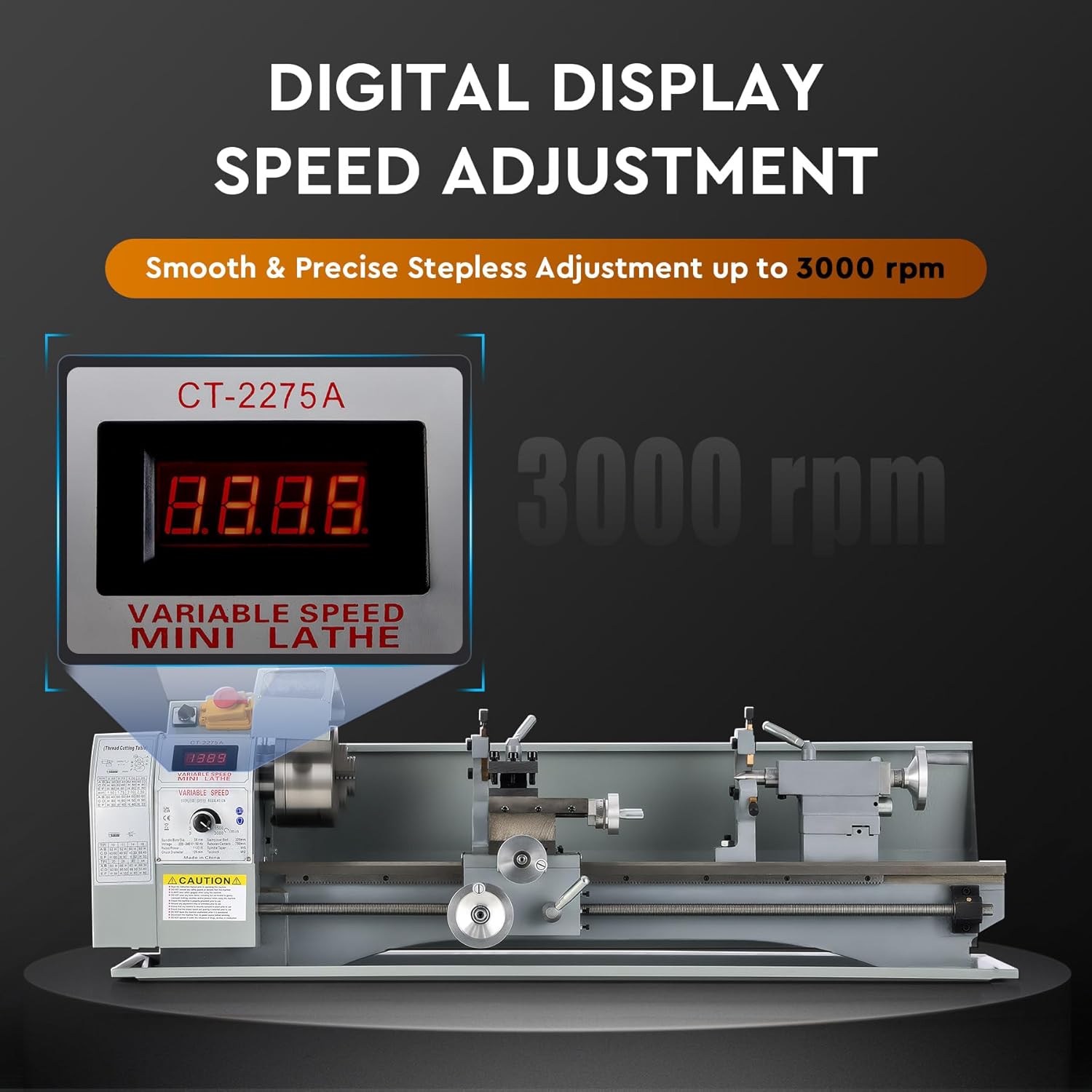
- Digital Display Speed Adjustment: Provides precise and stepless speed control up to 2250 RPM (or 3000 RPM as per some images/specs). The digital readout ensures accurate speed settings.
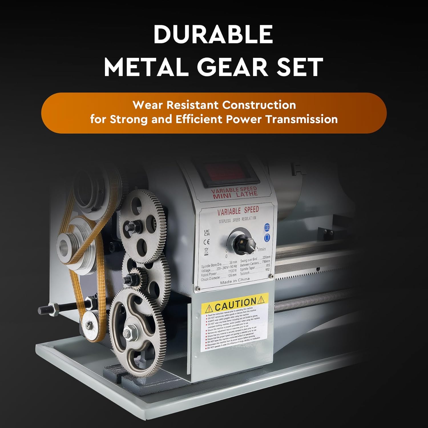
- Robust Construction: The metal bed is made of high-quality iron, ensuring stability and durability. Equipped with wear-resistant nylon gears for precise rotation.
- 3-Jaw Self-Centering Chuck: Securely holds cylindrical workpieces. Includes a splash guard for safety.
- Adjustable 4-Way Tool Post: Allows for easy changing of cutting tools and angles for various operations like chamfering.
- Dual V-Shaped Guide Rails: Ensures smooth and precise movement of the carriage and tailstock.
- Wide Application: Suitable for turning, drilling, threading, and cutting operations on various materials.

4. Setup
4.1 Unpacking and Inspection
- Carefully remove the lathe from its packaging. Retain all packaging materials for future transport or return.
- Inspect the machine for any signs of damage during transit. Report any damage to the carrier and supplier immediately.
- Verify that all components and accessories listed in the packing list are present.
4.2 Placement and Leveling
- Place the lathe on a sturdy, level workbench or stand capable of supporting its weight (approximately 75 kg).
- Ensure adequate clearance around the machine for safe operation and chip removal.
- Use a spirit level to check the machine's level. Adjust the feet or shims as necessary to ensure the bed is perfectly level. Proper leveling is crucial for accurate machining.
4.3 Power Connection
- Ensure the power supply matches the voltage and frequency requirements specified on the machine's nameplate (e.g., 220V).
- Connect the machine to a grounded electrical outlet. Do not use extension cords unless absolutely necessary, and ensure they are rated for the machine's power requirements.
- Before plugging in, ensure the power switch is in the "OFF" position.
4.4 Initial Cleaning and Lubrication
- Clean all protective grease and oil from the machine's surfaces, especially the bedways, lead screw, and chuck, using a suitable degreaser.
- Apply a thin coat of machine oil to all moving parts, including the bedways, lead screw, and gears, as specified in the maintenance section.
5. Operating Instructions
This section covers basic operational procedures. Always refer to the safety instructions before starting any operation.
5.1 Power On/Off and Emergency Stop

- Power On: Press the green "ON" button. The digital display will illuminate.
- Power Off: Press the red "OFF" button.
- Emergency Stop: In case of an emergency, press the large red mushroom-head button. This will immediately cut power to the motor. To reset, twist the button clockwise and then press the green "ON" button.
5.2 Spindle Speed Adjustment
- The lathe features variable speed control. Use the speed adjustment knob on the control panel to set the desired RPM.
- The digital display will show the current spindle speed. Adjust speed according to the material and operation being performed.
5.3 Workpiece Clamping (3-Jaw Chuck)
- Insert the workpiece into the 3-jaw chuck.
- Use the chuck key to tighten the jaws evenly until the workpiece is securely clamped. Remove the chuck key immediately after tightening to prevent it from being ejected during operation.
- Ensure the workpiece is centered and runs true before beginning any cutting operation.
5.4 Tool Post and Tool Bit Setup

- Select the appropriate cutting tool for the task.
- Insert the tool bit into the tool post and secure it firmly with the locking screws.
- Adjust the height of the tool bit so that its cutting edge is exactly on the centerline of the workpiece. Use shims if necessary.
- The 4-way tool post allows for quick changes and angular adjustments.
5.5 Tailstock Operation

- The tailstock can be moved along the bed and locked in position using its clamping lever.
- The tailstock quill can be extended or retracted using the handwheel and locked with the quill lock.
- Use a live center in the tailstock to support long workpieces during turning operations.
- Drill bits can be mounted in the tailstock for drilling operations.
5.6 Feed and Threading Operations
- The lead screw enables automatic feeding of the carriage for smooth cuts and precise thread cutting.
- Refer to the gear chart (if provided with the machine) for setting up the correct gears for specific thread pitches.
- Engage the half-nut lever for threading operations.
6. Maintenance
Regular maintenance is crucial for the longevity and performance of your lathe. Always disconnect power before performing maintenance.
- Daily Cleaning: After each use, clean chips and debris from the machine, especially from the bedways, lead screw, and chuck. Use a brush or air gun (with caution and eye protection).
- Lubrication: Regularly lubricate all moving parts, including the bedways, lead screw, cross slide, compound rest, and tailstock quill. Use high-quality machine oil. Check the gear train for proper lubrication.
- Gear Inspection: Periodically inspect the gears for wear or damage. Replace worn gears to maintain precision.
- Chuck Maintenance: Clean and lightly lubricate the chuck jaws and scroll plate to ensure smooth operation and proper gripping.
- Belt Tension: Check the drive belt tension periodically. Adjust if too loose or too tight.
- Electrical Inspection: Periodically check the power cord and connections for any signs of damage.
7. Troubleshooting
This section addresses common issues you might encounter. For problems not listed here, contact customer support.
| Problem | Possible Cause | Solution |
|---|---|---|
| Machine does not power on. | No power supply; Emergency stop engaged; Faulty switch. | Check power connection; Reset emergency stop button; Inspect power switch. |
| Spindle does not rotate or rotates slowly. | Incorrect speed setting; Drive belt loose or broken; Motor issue. | Adjust speed knob; Check and adjust/replace drive belt; Contact support if motor issue suspected. |
| Poor surface finish on workpiece. | Dull cutting tool; Incorrect cutting speed or feed rate; Workpiece not securely clamped; Machine vibration. | Sharpen or replace tool; Adjust speed/feed; Re-clamp workpiece; Check machine leveling and stability. |
| Excessive noise or vibration. | Loose components; Worn bearings or gears; Unbalanced workpiece. | Tighten all fasteners; Inspect bearings/gears for wear; Ensure workpiece is balanced; Re-level machine. |
| Digital display not working. | Loose connection; Faulty display unit. | Check connections; Contact support for replacement. |
8. Specifications
Technical specifications for the CREWORKS 220x750mm 1100W Metal Lathe.

| Feature | Detail |
|---|---|
| Model | MLM-SERIES (220x750mm) |
| Material | Steel |
| Rated Power | 1.5 HP (1100W) |
| Swing Over Bed | 220 mm (8.7 in.) |
| Spindle Bore | 38 mm (1.5 in.) |
| Tailstock Taper | MT#2 |
| Spindle Taper | MT#5 |
| Metric Thread Range | 0.5–3 mm |
| Inch Thread Range | 8–44 tpi |
| Center Distance | 750 mm (29.5 in.) |
| Chuck Diameter | 125 mm (5 in.) |
| Max. Spindle Speed | 3000 rpm |
| Net Weight | 75 kg (165.3 lb.) |
| Dimensions (Package) | 122 x 51 x 48.5 cm |
9. Warranty and Support
For warranty information, please refer to the terms and conditions provided at the time of purchase or contact your retailer. This product typically comes with a standard return policy (e.g., 30 days from purchase).
For technical support, spare parts, or any operational queries, please contact CREWORKS customer service or your authorized dealer. Have your model number (MLM-SERIES) and purchase date ready when contacting support.
Contact Information: Refer to your purchase documentation or the CREWORKS official website for the most current contact details.
10. Product Videos
No official product videos from the seller were available in the provided data for embedding. Please refer to the manufacturer's website or product page for any available video resources.


