
Matek Systems CRSF-PWM-6
Matek Systems CRSF-PWM-6 CRSF to PWM Converter Instruction Manual
Model: CRSF-PWM-6 | Brand: Matek Systems
1. Introduction
This manual provides detailed instructions for the installation, setup, and operation of the Matek Systems CRSF-PWM-6 CRSF to PWM Converter. This device is designed to convert CRSF protocol signals into PWM outputs, making it suitable for various RC applications including fixed-wing aircraft, gliders, cars, and boats. Please read this manual thoroughly before use to ensure proper functionality and safety.
2. Features
- Compatible exclusively with CRSF protocol receivers (including 433MHz, 868MHz, 915MHz, 2.4GHz).
- Provides 6x PWM outputs.
- PWM frequency is configurable (default 50Hz, options include 100, 160, 330, 400Hz).
- Includes 2x UARTs for Receiver and GPS connectivity.
- Supports telemetry IDs: RxBt, Curr, Capa, Bat%, GPS, GSpd, Hdg, Alt, Sats.
- 36V maximum battery voltage sense with a built-in 1K:10K voltage divider.
- Compatible with external current sensors (0~3.3V).
- Configurable Vbat and Current sensor scale.
- Automatic failsafe value setting.
- Firmware upgradeable.
- Compact dimensions: 25mm x 16mm, lightweight at 1.3g.
3. Specifications
| Attribute | Value |
|---|---|
| Dimensions | 25mm x 16mm |
| Weight | 1.3g |
| Rated Voltage (5V pad) | 4~9V |
| Rated Voltage (Vbat) | 0~36V |
| Rated Voltage (Curr) | 0~3.3V |
| PWM Outputs | 6 |
| UARTs | 2 (for Receiver and GPS) |
| Telemetry IDs | RxBt, Curr, Capa, Bat%, GPS, GSpd, Hdg, Alt, Sats |
| 5V Regulator | Not built-in |

Image: Matek Systems CRSF-PWM-6 Converter showing dimensions (25mm x 16mm) and weight (1.3g).
4. Pinouts and Pads
The CRSF-PWM-6 converter features various pins and pads for connectivity and configuration. Understanding these is crucial for proper setup.
- Tx1/Rx1 (UART1): For CRSF protocol receiver.
- Tx2/Rx2 (UART2): For GPS/firmware update/setting parameters.
- 1-10: CH1-CH10 PWM outputs.
- Curr: Current sensor input (0-3.3V).
- Vbat: Battery voltage sensing (0-36V).
- G: Ground.
- 4V5 pad: 5V pad voltage -0.3V. Ensure the voltage on the 5V pad is not higher than the receiver and GPS rated voltage.

Image: Detailed view of the Matek Systems CRSF-PWM-6 board, highlighting pinouts and pads for various connections.
5. Setup
5.1. Binding Procedure
To bind the CRSF-PWM-6 converter to your CRSF protocol transmitter, follow these steps:
- Connect the CRSF-PWM-6 to power.
- Quickly disconnect and reconnect power to the converter three times. This will put the device into binding mode.
- On your CRSF protocol transmitter, initiate the binding process according to your transmitter's manual.
- The converter's LED status will indicate successful binding.
5.2. Wiring Diagram
Refer to the diagram below for typical wiring connections for the CRSF-PWM-6 converter in an RC setup. This diagram illustrates connections for ESC, battery, and GPS modules.
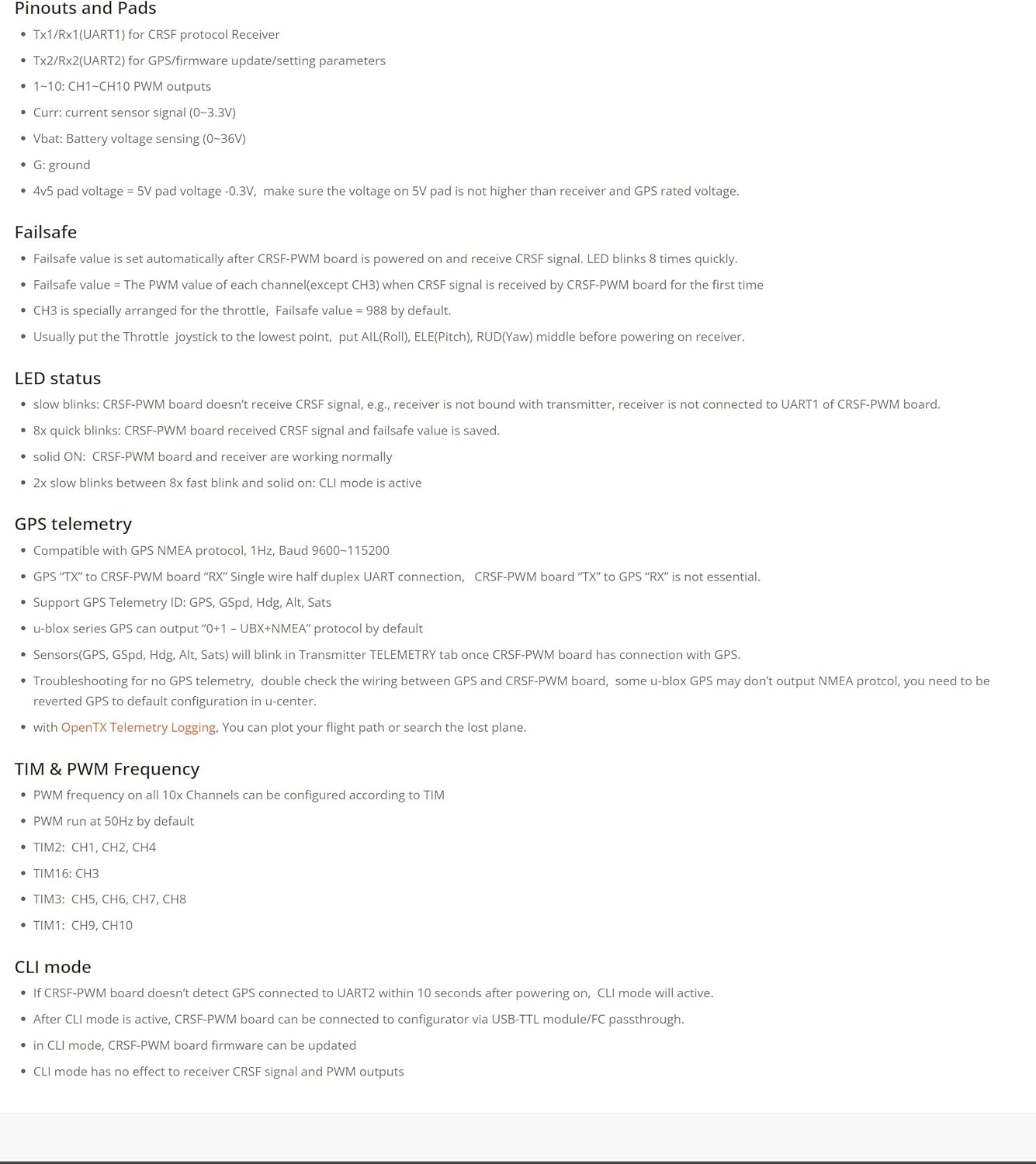
Image: Wiring diagram showing connections for the CRSF-PWM-6 with an ESC, battery, and GPS module.
Important Tips:
- If the receiver and PWM board are soldered together through the Dupont pins, you may remove 2x 0-ohm resistors when you want to flash receiver via UART.
- Bridge the pad with a drop of tin after flashing.
- You may also flash the receiver via WiFi.
- Dupont 2.54 pins are shipped unsoldered.
- Receiver is not included in the package.
WARNING: Double-check the receiver and GPS rated voltage. Make sure the voltage on the 5V pad is not higher than the receiver and GPS rated voltage.
6. Operating Instructions
6.1. PWM & TIM Frequency
- PWM frequency on all 10 channels can be configured according to TIM.
- PWM runs at 50Hz by default.
- TIM2: CH1, CH2, CH4
- TIM16: CH3
- TIM3: CH5, CH6, CH7, CH8
- TIM1: CH9, CH10
6.2. LED Status Indicators
- Slow blinks: CRSF-PWM board does not receive CRSF signal, or the receiver is not bound with the transmitter, or the receiver is not connected to UART1 of the CRSF-PWM board.
- 8x quick blinks: CRSF-PWM board received CRSF signal and failsafe value is saved.
- Solid ON: CRSF-PWM board and receiver are working normally.
- 2x slow blinks between 8x fast blink and solid ON: CLI mode is active.
6.3. GPS Telemetry
- Compatible with GPS NMEA protocol, 1Hz, Baud 9600-115200.
- GPS "Tx" to CRSF-PWM board "Rx". Single wire half duplex UART connection, CRSF-PWM board "Tx" to GPS "Rx" is not essential.
- Supports GPS Telemetry IDs: GSpd, Hdg, Alt, Sats.
- U-blox series GPS can output "DPL-UBX+NMEA" protocol by default.
- Sensors (GPS, GSpd, Hdg, Alt, Sats) will blink in Transmitter TELEMETRY tab once CRSF-PWM board has connection with GPS.
- Troubleshooting for no GPS telemetry: double-check the wiring between GPS and CRSF-PWM board. Some U-blox GPS may not output NMEA protocol; you need to revert GPS to default configuration in U-center.
- With OpenTX Telemetry Logging, you can plot your flight path or search the lost plane.
6.4. CLI Mode
- If the CRSF-PWM board doesn't detect GPS connected to UART2 within 10 seconds after powering on, CLI mode will activate.
- After CLI mode is active, the CRSF-PWM board can be connected to a configurator via a USB-TTL module/FC passthrough.
- In CLI mode, CRSF-PWM board firmware can be updated.
- CLI mode has no effect on receiver CRSF signal and PWM outputs.
7. Failsafe Configuration
Proper failsafe configuration is critical for safe operation of your RC model.
- Failsafe value is set automatically after the CRSF-PWM board is powered on and receives a CRSF signal. The LED blinks 8 times quickly to confirm.
- The failsafe value is the PWM value of each channel (except CH3) when a CRSF signal is received by the CRSF-PWM board for the first time.
- CH3 is specially arranged for the throttle, with a failsafe value of 988 by default.
- To set failsafe, usually push the Throttle joystick to the lowest point, then pull All (Roll), Ele (Pitch), RUD (Yaw) middle before powering on the receiver.
8. Maintenance
To ensure the longevity and optimal performance of your CRSF-PWM-6 converter, consider the following maintenance guidelines:
- Keep the board clean and free from dust, dirt, and moisture.
- Regularly inspect all connections for secure fit and signs of wear or corrosion.
- Ensure proper ventilation to prevent overheating, especially during extended use.
- Store the converter in a dry, cool environment when not in use.
- Periodically check for firmware updates from Matek Systems to benefit from performance improvements and bug fixes.
9. Troubleshooting
If you encounter issues with your CRSF-PWM-6 converter, refer to the following common problems and solutions:
- No CRSF Signal (Slow Blinking LED):
- Verify the receiver is correctly bound to the transmitter.
- Check that the receiver is properly connected to UART1 on the CRSF-PWM board.
- Ensure the transmitter is powered on and transmitting.
- No GPS Telemetry:
- Double-check all wiring between the GPS module and the CRSF-PWM board.
- Confirm that your U-blox GPS module is configured to output NMEA protocol. If not, revert it to default configuration using U-center software.
- Incorrect PWM Output:
- Verify the PWM frequency settings in CLI mode if custom frequencies are desired.
- Ensure correct channel mapping in your transmitter and flight controller (if applicable).
- Power Issues:
- Check the input voltage to the 5V pad and Vbat to ensure they are within the specified ranges (4~9V for 5V pad, 0~36V for Vbat).
- Confirm that the voltage on the 4V5 pad does not exceed the rated voltage of your receiver and GPS module.
10. Warranty and Support
For warranty information, technical support, or further assistance, please refer to the official Matek Systems website or contact their customer service directly. Keep your purchase receipt as proof of purchase for any warranty claims.
Ask a question about this manual
Ask about setup, troubleshooting, compatibility, parts, safety, or missing instructions. Manuals+ will review the question and use this page’s manual context to help answer it.