1. Product Overview
The Geevorks Portable Spot Welder is a DIY tool designed for spot welding 18650 batteries and other small battery welding applications. It features a microcomputer-controlled output pulse for precise welding and offers both automatic and manual touch welding modes. This device is compatible with various power supplies, including lithium batteries and 12V car batteries.


2. Package Contents
Verify that all items listed below are included in your package:
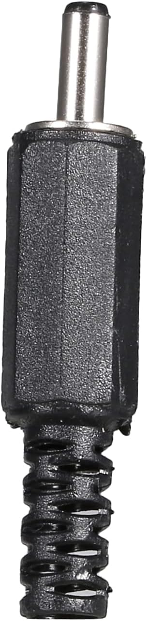
- 1 x Controller
- 2 x Welding pens (Red and Blue)
- 2 x Power input lines (Red and Blue)
- 1 Pair x U-shaped cold-pressed terminals


3. Specifications
| Material | Metal |
| Input Line Length | Approximately 20 cm (7.87 in) |
| Welding Pen Length | Approximately 30 cm (11.81 in) |
| Color | Red+Blue+Black |
| Compatible Batteries | 18650 lithium battery (not included), 12V car battery, 3S 40-70C 5000mAh lithium battery |
| Welding Thickness | 0.1-0.12mm nickel strip |
| Item Weight | 9.6 ounces |
| Package Dimensions | 8.43 x 7.01 x 2.28 inches |
4. Setup Instructions
4.1 Power Connection
The controller is supplied with a 20cm long 10AWG input wire. One end of this wire is pre-crimped with a U-shaped terminal. Connect this U-shaped terminal to the control power input terminal on the spot welder. The other end of the input wire should be prepared according to your chosen power supply (e.g., a lithium battery or a 12V car battery). Ensure correct polarity when connecting to the power source; do not connect the negative electrode incorrectly.

5. Operating Instructions
5.1 Power On/Off
Locate the power switch beneath the control board. Press the power switch to turn the device on. Wait for approximately 3 seconds until a buzzer sound is heard and the LCD screen illuminates, indicating that the boot process is complete. To shut down the device, press the power switch again.
5.2 Screen Description and Parameter Adjustment
The LCD screen displays welding parameters such as "WELD ENERGY", "INPUT voltage", and "WELD WAY" (Manual/Automatic). Use the control buttons (typically up/down arrows) on the panel to navigate and adjust these parameters. The device has 99 adjustable gears for welding power. It is crucial to not exceed 50 gears, as operating above this level may lead to damage or burning of components.

5.3 Welding Procedure
- Prepare Welding Pins: Ensure the welding pins are clean. Polishing the welding pin tips into a rounded shape can improve welding effectiveness.
- Select Welding Mode: The device supports both manual and automatic welding modes. Choose the mode that best suits your application.
- Position Workpiece: Place the nickel strip and battery in the desired welding position.
- Execute Weld:
- Automatic Mode: In automatic mode, the welding process initiates when the welding pins make contact with the nickel strip and the battery, and a stable connection is detected. The output pulse is then automatically triggered.
- Manual Mode: In manual mode, welding is initiated by pressing the manual trigger button after the welding pins are correctly positioned on the workpiece.
- Inspect Weld: After each weld, inspect the joint for strength and quality.
6. Safety Warnings and Precautions
- Important: Do not exceed 50 gears for welding power. Operating above this setting may cause burning or damage to the unit.
- Ensure the power supply is within the specified range (12V car battery or 3S 40-70C 5000mAh lithium battery). Insufficient or excessive power can affect performance and safety.
- When connecting the power input lines, ensure correct polarity. Incorrect connection of the negative electrode can damage the controller.
- Keep the welding pins clean and sharp for optimal performance and to prevent poor welds.
- During welding, heat is generated. Avoid placing flammable materials such as wooden blocks directly beneath the welding area, as they can melt or catch fire.
- If the welding pin is not firmly crimped on the nickel strip and is loose, there will be fire explosion or no welding. Ensure a firm connection.
- Always wear appropriate personal protective equipment, including safety glasses, when operating the spot welder.
7. Troubleshooting
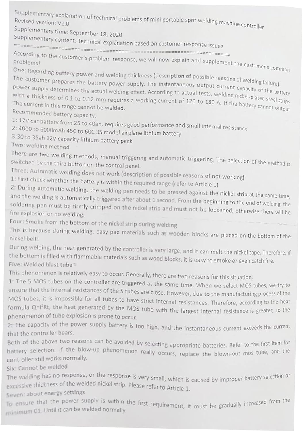
This section addresses common issues and their potential solutions. Refer to the supplementary explanation document (Image 6.1) for more detailed technical insights.
7.1 Automatic Welding Not Working
- Check Battery: Verify that the power supply battery is within the required voltage range and has sufficient capacity. A weak battery can prevent proper operation.
- Welding Pin Contact: Ensure the welding pins are firmly pressed against the nickel strip and the battery. If the connection is loose, the automatic trigger may not activate, or a "fire explosion" (sparking without welding) may occur.
7.2 Smoke from Nickel Strip During Welding
- This can occur if the welding pin is not firmly crimped to the nickel strip, leading to poor contact and excessive heat. Ensure a secure connection.
- Also, ensure no flammable materials are directly beneath the welding area, as the heat generated can cause them to smoke or ignite.
7.3 Welded Blast Tube / MOSFET Failure
- This issue is often related to the internal resistances of the MOSFETs. If the power supply battery has a very high current output, or if the resistance to current flow is not optimized (e.g., long or thin input wires), it can lead to excessive heat and MOSFET failure.
- Ensure your power supply battery is appropriate for the device and that input wiring is of adequate gauge to minimize resistance.
7.4 No Response or Weak Weld
- This is typically caused by improper battery selection or excessive thickness of the nickel strip being welded. Refer to the power supply recommendations in Section 3 and ensure the nickel strip thickness is within the 0.1-0.12mm range.
- Verify that the energy setting (gears) is appropriate for the material and power source.
8. Maintenance
- Clean Welding Pins: Regularly clean the tips of the welding pens to remove any residue or oxidation. This ensures consistent electrical contact and optimal welding performance.
- Inspect Cables: Periodically check all cables and connections for signs of wear, fraying, or damage. Replace any damaged components immediately.
- Storage: Store the spot welder in a dry, clean environment away from direct sunlight and extreme temperatures.
- Battery Care: If using a separate lithium battery for power, follow the manufacturer's guidelines for charging, discharging, and storage to prolong its lifespan and ensure safety.
9. Warranty and Support
For warranty information or technical support, please refer to the documentation provided with your purchase or contact Geevorks customer service through the retailer where the product was acquired. Keep your proof of purchase for warranty claims.