
1. Introduction
The Y&H 10A PWM Solar Charge Controller is designed to manage the power flow from solar panels to batteries in off-grid solar applications. It features efficient PWM charging to extend battery life and enhance system performance. This controller is compatible with 12V/24V battery systems and is equipped with an LCD display for easy monitoring and parameter configuration.
This manual provides essential information for the safe and effective installation, operation, and maintenance of your solar charge controller.

Image 1.1: Front view of the Y&H 10A PWM Solar Charge Controller, showing the LCD screen, control buttons, and dual USB ports.
2. Product Features
- Automatic System Voltage Recognition: Automatically detects 12V or 24V system voltage.
- Efficient PWM Charging: Utilizes Pulse Width Modulation for optimized battery charging, prolonging battery lifespan.
- LCD Display: Provides real-time status and data, including battery voltage, charge/discharge current, and operating mode.
- Dual USB Output: Two 5V/2.5A (max) USB ports for charging mobile devices.
- Comprehensive Protections: Includes overcurrent, short-circuit, inverse connection, low voltage, and overcharge protection.
- Adjustable Parameters: User-configurable charging and discharging parameters.
- Built-in Industrial Microcontroller: Ensures stable and reliable operation.

Image 2.1: Detailed view of the controller's LCD display and labeled terminals. The display shows battery voltage and icons for solar panel, battery, and load. Terminals are labeled for solar panel, load, and battery connections.
3. Safety Information
- This charge controller is designed exclusively for lead-acid batteries: OPEN, AGM, and GEL types. Do not use with other battery types (e.g., lithium-ion).
- Ensure correct polarity when connecting all components to prevent damage to the controller and other equipment.
- Install the controller in a well-ventilated area, away from flammable materials and direct sunlight.
- The controller will automatically shut down if battery voltage drops below 8V to protect the battery.
- Always connect the battery first, then the solar panel, and finally the load. Disconnect in the reverse order.
4. Installation
Follow these steps for proper installation of the solar charge controller:
- Prepare Wiring: Ensure all wires are appropriately sized (12 AWG recommended for RBL-10A) and have proper insulation.
- Connect Battery: First, connect the battery to the controller's battery terminals. Ensure correct polarity (+ to + and - to -). The LCD display should illuminate.
- Connect Solar Panel: Next, connect the solar panel to the controller's solar panel terminals. Again, observe correct polarity.
- Connect Load: Finally, connect your DC loads to the controller's load terminals.
- Secure Connections: Unscrew the terminal screws, insert the wire into the small hole, and tighten the screw securely to ensure good contact.
Important: Always connect the battery first, then the solar panel, and then the load. Disconnect in the reverse order: load, then solar panel, then battery.

Image 4.1: Wiring diagram illustrating the connection sequence for solar panels, battery, and DC loads to the solar charge controller. An optional inverter for AC loads is also shown.
5. Operation
5.1 LCD Display and Buttons
The LCD display shows various system parameters. The controller has three buttons:
- MENU Button: Short press to switch between different display interfaces. Long press to enter/exit parameter setting mode.
- UP Button: Press to increase a value during parameter setting.
- DOWN Button: Press to decrease a value during parameter setting.
5.2 USB Charging
The controller features dual USB ports (5V/2.5A max) for charging compatible mobile phones, tablets, and other USB-powered devices.
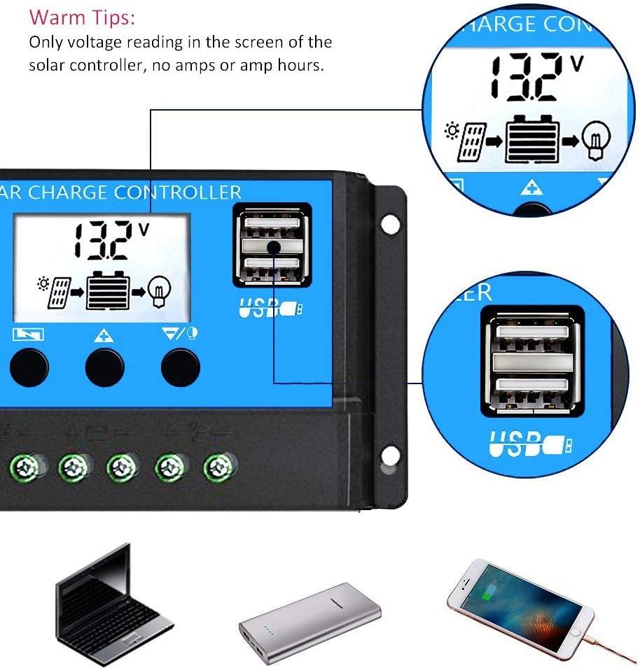
Image 5.1: Close-up view of the dual USB ports on the controller. A note indicates that the screen displays only voltage readings, not amperage or amp-hours.
6. Settings and Parameter Configuration
The controller allows users to browse different interfaces and configure various parameters. To enter parameter setting mode, long press the MENU button when viewing interfaces 2-5. Use the UP and DOWN buttons to adjust values. Long press MENU again to exit setting mode or to restore default parameters.
6.1 Display Interfaces and Adjustable Parameters
- Main Display: Shows current battery voltage.
- Float Voltage: The voltage at which the battery is maintained after being fully charged. (Adjustable)
- Discharge Reconnect Voltage: The voltage at which the load will be reconnected after being disconnected due to low battery. (Adjustable)
- Discharge Stop Voltage: The voltage at which the load will be disconnected to protect the battery from over-discharge. (Adjustable)
- Battery Type: Select the battery type (B01 Sealed, B02 Gel, B03 Flood). (Adjustable)
- Work Mode: Configures load output timing (e.g., 24 hours, 1-23 hours, 0 hour). (Adjustable)
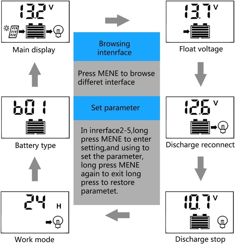
Image 6.1: Flowchart illustrating the navigation through the controller's LCD display interfaces and the steps for setting parameters such as float voltage, discharge reconnect, discharge stop, battery type, and work mode.
7. Specifications
The following table details the technical specifications for the Y&H RBL-10A Solar Charge Controller:
| Parameter | RBL10 (10A Model) |
|---|---|
| Installation Wire Gauge | 12 AWG |
| Charge Current | 10A |
| Discharge Current | 10A |
| Battery Voltage | 12V/24V Auto Adapt |
| Float Voltage | 13.7V (Adjustable) |
| Discharge Stop Voltage | 10.7V (Adjustable) |
| Discharge Reconnect Voltage | 12.6V (Adjustable) |
| Self-Consume | <10mA |
| USB Output | 5V/2A Max |
| Operating Temperature | -35°C to +60°C |
| Max Solar Input Voltage | <50V |
| Max Input Power (12V System) | 120W |
| Max Input Power (24V System) | 240W |
| Equalization (B01 Sealed) | 14.4V |
| Equalization (B02 Gel) | 14.2V |
| Equalization (B03 Flood) | 14.6V |
| Dimensions | 5.91 x 3.07 x 1.38 inches (15 x 7.8 x 3.5 cm) |
| Item Weight | 5.6 ounces |

Image 7.1: A table detailing the specifications for different models (RBL10, RBL20, RBL30) of the Y&H solar charge controller, including charge/discharge current, battery voltage, and dimensions.
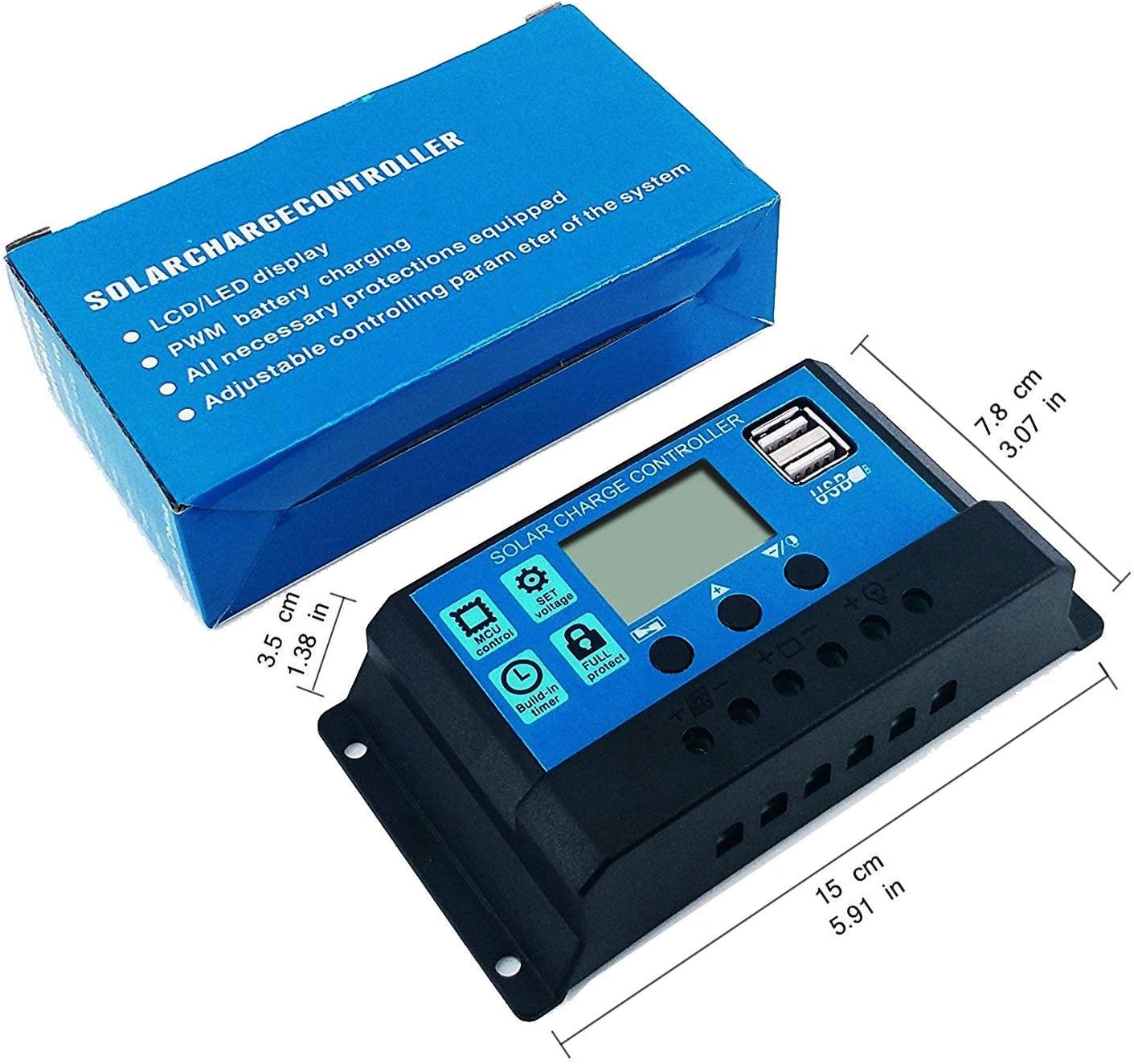
Image 7.2: Diagram illustrating the physical dimensions of the Y&H Solar Charge Controller, showing measurements in both centimeters and inches.
8. Troubleshooting
This section provides general guidance for common issues. For specific problems, refer to the contact information in the Warranty and Support section.
- No Display/Power: Check battery connections and ensure the battery has sufficient voltage (above 8V).
- Battery Not Charging: Verify solar panel connections and ensure adequate sunlight. Check for any shading on the solar panels.
- Load Not Working: Check load connections. Ensure the battery voltage is above the discharge reconnect voltage. Verify load mode settings.
- Overcharge/Over-discharge Protection: The controller is designed with built-in protections. If the battery is overcharged or over-discharged, the controller will automatically adjust or disconnect to protect the battery.
9. Maintenance
Regular maintenance helps ensure the longevity and optimal performance of your solar charge controller and system.
- Inspect Connections: Periodically check all wiring connections for tightness and corrosion.
- Clean Controller: Keep the controller clean and free from dust and debris. Use a dry cloth for cleaning.
- Battery Inspection: Regularly inspect your battery for any signs of damage, corrosion, or swelling. Ensure proper ventilation around the battery.
- Solar Panel Cleaning: Clean solar panels periodically to remove dirt, dust, or leaves that may reduce efficiency.
10. Warranty and Support
The Y&H 10A PWM Solar Charge Controller comes with a 12-month warranty and lifetime technical support.
If you encounter any issues or have questions regarding the product, please contact Y&H customer support through the Amazon email system. We are committed to providing assistance and will arrange for a refund or replacement if necessary.