1. Product Overview
The Reland Sun XH-M601 is a 12V intelligent battery charging control board designed to manage the charging process of 12V storage batteries. It automatically controls the power supply to ensure optimal charging and prevent overcharging or undercharging. This module features adjustable start and disconnect charging voltages, providing flexibility for various battery types and applications.
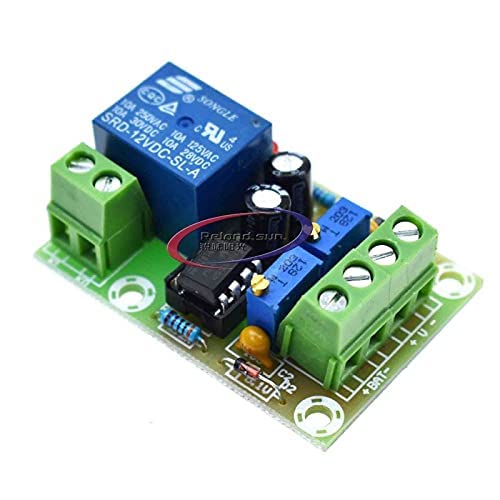
Figure 1: Front view of the XH-M601 Battery Charging Control Board, showing the relay, potentiometers, and terminal blocks.
2. Specifications
- Name: 12V charger power control board
- Model: XH-M601
- Power Supply Voltage: 13.8V - 14.8V
- Relay Operating Voltage: 12.4V
- Relay Disconnect Voltage: 14.8V
- Voltage Tolerance: +/-0.1V
- Voltage Detection Method: DC voltmeter
- Charging Type: 12V storage battery
- Potentiometer Adjustment: RP1 (Start Charging Voltage), RP2 (Disconnect Charging Voltage)
- Dimensions: 50mm x 32mm x 18mm
3. Setup
Follow these steps to set up the XH-M601 battery charging control board:
- Power Connection: Connect the power supply (13.8V-14.8V DC) to the designated input terminals on the board. Ensure correct polarity.
- Battery Connection: Connect the 12V storage battery to the battery terminals on the board. Observe correct polarity (+ to + and - to -).
- Load Connection (Optional): If a load is to be powered directly from the battery while charging, ensure it is connected appropriately to the battery terminals or a separate power distribution point.
- Initial Voltage Check: Before connecting the battery, verify the power supply voltage is within the specified range.
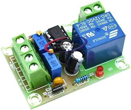
Figure 2: Detailed view of the XH-M601 board, highlighting the input/output terminals and adjustment potentiometers.
4. Operating Instructions
The XH-M601 board operates automatically based on the set voltage thresholds. When the battery voltage drops below the start charging voltage (set by RP1), the relay will activate, allowing current to flow to the battery for charging. When the battery voltage reaches the disconnect charging voltage (set by RP2), the relay will deactivate, stopping the charging process.
This automatic control ensures the battery is charged when needed and prevents overcharging once full, extending battery life.
5. Potentiometer Adjustment
The board features two potentiometers, RP1 and RP2, for adjusting the charging thresholds:
- RP1 (Start Charging Voltage): This potentiometer adjusts the low voltage threshold at which the battery charging process begins.
- Turning clockwise will increase the start charging voltage.
- Turning counter-clockwise will decrease the start charging voltage.
- RP2 (Disconnect Charging Voltage): This potentiometer adjusts the high voltage threshold at which the battery charging process stops.
- Turning clockwise will increase the disconnect charging voltage.
- Turning counter-clockwise will decrease the disconnect charging voltage.
Important: Use a DC voltmeter to accurately measure the battery voltage while adjusting the potentiometers to set the desired thresholds. Make small adjustments and observe the relay's behavior.
6. Maintenance
The XH-M601 board requires minimal maintenance. To ensure optimal performance and longevity:
- Keep the board clean and free from dust and debris.
- Ensure proper ventilation to prevent overheating.
- Periodically check all connections for tightness and corrosion.
- Avoid exposing the board to moisture or extreme temperatures.

Figure 3: Back view of the XH-M601 board, illustrating the PCB layout and solder points.
7. Troubleshooting
If you encounter issues with the XH-M601 board, consider the following troubleshooting steps:
- No Power/Indicator Light Off:
- Check the power supply voltage and ensure it is within the 13.8V-14.8V range.
- Verify all power connections are secure and correctly polarized.
- Battery Not Charging:
- Ensure the battery voltage is below the RP1 (start charging) threshold.
- Check battery connections for proper polarity and secure contact.
- Inspect the relay for proper operation (listen for a click when voltage drops below RP1).
- Battery Overcharging:
- Verify the RP2 (disconnect charging) threshold is set correctly and is not too high.
- Ensure the relay is disengaging when the voltage reaches the RP2 threshold.
- Inaccurate Voltage Readings:
- Use a calibrated external voltmeter to cross-reference readings.
- Ensure connections are clean and free of corrosion, which can affect voltage sensing.
8. Package Contents
The package for the Reland Sun XH-M601 Battery Charging Control Board typically includes:
- 1 x XH-M601 12V Battery Charging Control Board