1. Introduction
This manual provides detailed instructions for the installation, setup, operation, and maintenance of the GalaxyElec Micro OSD V2 Module. This module is designed to integrate with Pixhawk4, Pixhawk4 Mini, and Durandal flight controllers, providing essential on-screen display (OSD) functionality for various remote-controlled aircraft, including drones.
Please read this manual thoroughly before using the product to ensure correct operation and to prevent damage.
2. Product Overview
The Micro OSD V2 Module is a compact and efficient on-screen display unit that overlays critical flight data onto your video feed. This allows pilots to monitor parameters such as battery voltage, flight mode, GPS coordinates, and more, directly on their FPV goggles or monitor. It is compatible with flight controllers utilizing the ATmega328P with Arduino bootloader and MAX7456 monochrome OSD chip.

Figure 2.1: Front view of the GalaxyElec Micro OSD V2 Module. This image shows the compact design of the OSD module with its main components and connectors visible.
3. Specifications
- Processor: ATmega328P with Arduino bootloader
- OSD Chip: MAX7456 monochrome on-screen display
- Programming Interface: Standard 6-pin ISP header
- Video System Compatibility: Solder jumper for PAL video option
- Test Points: Exposed test points for HSYNC and LOS
- Dimensions: 17.5mm x 35mm
- Weight: 3g
4. Package Contents
The following items are included in your package:
- 1x Micro OSD V2 Module
- 1x GH 6P Cable
- 1x GH 4P Cable
- 1x GH 3P Cable

Figure 4.1: The Micro OSD V2 Module shown with its accompanying connection cables. This image illustrates all components included in the product package.
5. Setup and Wiring
Proper wiring is crucial for the correct functionality of the Micro OSD V2 Module. Follow the diagrams and instructions carefully.
5.1 Pinout Diagram
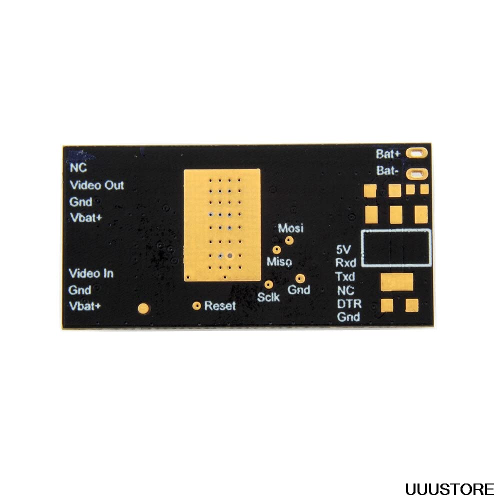
Figure 5.1: Back view of the Micro OSD V2 Module detailing the pin assignments for various connections. This diagram is essential for identifying the correct connection points.
- BAT+ / BAT-: Battery input for OSD power.
- VTx Port: Connects to Video Transmitter (VTx). Includes NC (No Connection), Video Out, GND, VBAT+.
- Camera Port: Connects to FPV Camera. Includes Video In, GND, VBAT+.
- TELEM Port: Telemetry connection to Flight Controller (5V, RXD, TXD, NC, DTR, GND).
- ISP Header: Standard 6-pin header for programming the ATmega328P.
5.2 Connection Diagram

Figure 5.2: Comprehensive wiring diagram illustrating how to connect the Micro OSD V2 Module to a Pixhawk4 flight controller, FPV camera, and video transmitter (VTx). This visual guide shows the flow of power and data.
- Connect to Flight Controller: Use the provided GH cables to connect the TELEM port of the OSD module to an available telemetry port on your Pixhawk4, Pixhawk4 Mini, or Durandal flight controller. Ensure RXD on OSD connects to TXD on FC, and TXD on OSD connects to RXD on FC. Connect 5V and GND accordingly.
- Connect Camera: Connect your FPV camera's video output to the "Video In" pin on the OSD module's Camera Port. Connect the camera's GND to the OSD's GND. The VBAT+ pin on the Camera Port can supply power to your camera, but ensure your camera's voltage requirements match.
- Connect Video Transmitter (VTx): Connect the "Video Out" pin on the OSD module's VTx Port to your video transmitter's video input. Connect the VTx's GND to the OSD's GND. The VBAT+ pin on the VTx Port can supply power to your VTx, but verify voltage compatibility.
- Power Connection: Connect the BAT+ and BAT- pads on the OSD module to your main flight battery or a regulated power source.
Important Note: The BAT+ pins on the VTx and Camera ports are directly connected to the main BAT+ input. Exercise caution and verify the maximum withstand voltage of your camera and video transmitter before connecting them to avoid damage.
6. Operating Instructions
Once the Micro OSD V2 Module is correctly wired and powered, it will begin overlaying data onto your video feed. The specific data displayed and its layout are typically configured through the flight controller's ground station software (e.g., Mission Planner, QGroundControl) or a dedicated OSD configuration tool.
- Initial Configuration: Refer to your flight controller's documentation for instructions on enabling and configuring OSD functionality. You may need to select the correct OSD type (e.g., MinimOSD compatible) and enable telemetry output to the OSD port.
- OSD Layout Customization: Most flight controller software allows you to customize which data elements are displayed (e.g., voltage, current, GPS, flight mode, artificial horizon) and their positions on the screen.
- PAL/NTSC Selection: If your camera or VTx uses a different video standard, ensure the solder jumper on the OSD module is set correctly for PAL or NTSC. Incorrect selection can result in a distorted or black screen.
7. Maintenance
The Micro OSD V2 Module is a robust electronic component, but proper care ensures its longevity and reliable performance.
- Keep Clean: Regularly inspect the module for dust, dirt, or debris. Use a soft, dry brush or compressed air to gently clean the board. Avoid using liquids.
- Protect from Elements: Ensure the module is protected from moisture, extreme temperatures, and direct sunlight. Consider using a protective enclosure if operating in harsh environments.
- Inspect Connections: Periodically check all wiring connections for looseness or damage. Secure any loose connections to prevent intermittent operation.
- Firmware Updates: While not frequently required, check the manufacturer's website or flight controller community forums for any available firmware updates for the OSD module. Follow update instructions carefully.
8. Troubleshooting
If you encounter issues with your Micro OSD V2 Module, refer to the following common problems and solutions:
| Problem | Possible Cause | Solution |
|---|---|---|
| No OSD display / Black screen |
|
|
| Garbled or flickering OSD text |
|
|
| No data displayed (e.g., voltage, GPS) |
|
|
9. Warranty and Support
This product is manufactured by GalaxyElec. For specific warranty information, please refer to the retailer's policy where the product was purchased. General support for the Micro OSD V2 Module can often be found through online communities dedicated to Pixhawk and RC drone electronics, as well as the manufacturer's official support channels if available.
Always ensure you are using the product within its specified operating parameters to maintain warranty validity.


