ELEGRP ELEGRP-50A-125V
ELEGRP 50A 125/250V NEMA 14-50R Receptacle & 14-30P/14-50P Plugs Instruction Manual
Model: ELEGRP-50A-125V
1. Introduction
This manual provides essential instructions for the safe installation, operation, and maintenance of your ELEGRP 50 Amps 125/250V NEMA 14-50R Range Oven Stove Receptacle and ELEGRP NEMA 14-30P & NEMA 14-50P 4-Prong Electric Dryer and Range Oven Stove Plugs. Please read this manual thoroughly before installation and use, and retain it for future reference.
2. Safety Information
WARNING: Risk of electric shock or fire. Improper installation or use can lead to serious injury or death. All electrical work should be performed by a qualified electrician and in accordance with all national and local electrical codes.
- Always turn off power at the circuit breaker or fuse box before installing or servicing the receptacle or plugs.
- Verify that the voltage and amperage ratings of your appliance match the receptacle and plug ratings.
- Ensure proper grounding to prevent electrical shock.
- Do not use if the product appears damaged.
- Keep children away from electrical outlets and wiring.
3. Product Overview
The ELEGRP NEMA 14-50R Receptacle is a flush-mount power outlet designed for heavy-duty applications such as electric ranges, ovens, and EV chargers. The ELEGRP NEMA 14-30P and 14-50P plugs are industrial-grade, straight-blade plugs for electric dryers and ranges, featuring interchangeable blades for versatility.
3.1 Receptacle Features (NEMA 14-50R)
- Type: NEMA 14-50R, 50 Amps, 125/250V
- Configuration: 3 Pole, 4 Wire, Grounding
- Mounting: Flush Mount, fits single and 2-gang box styles
- Construction: Heavy gauge galvanized steel mounting strap, durable nylon housing, brass contacts
- Wire Compatibility: Accepts #10, #8 to #4 AWG copper or aluminum wire
- Certifications: UL Listed

Image: ELEGRP NEMA 14-50R Receptacle. This image shows the front view of the 50 Amp, 125/250V NEMA 14-50R flush mount receptacle with its distinct blade configuration and UL listing mark.
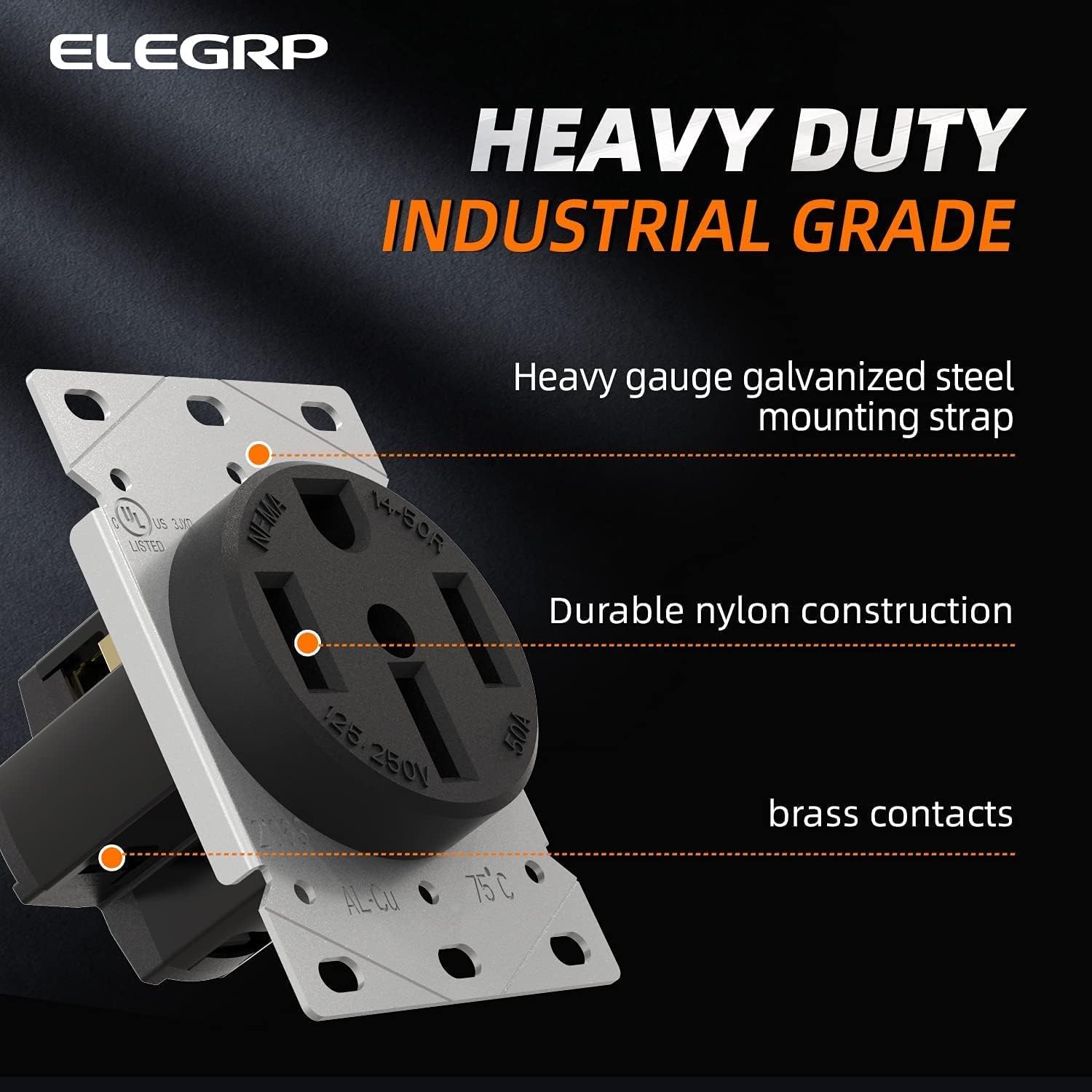
Image: ELEGRP NEMA 14-50R Receptacle Features. This image highlights the heavy-duty industrial grade construction, including the galvanized steel mounting strap, durable nylon housing, and brass contacts.
3.2 Plug Features (NEMA 14-30P & 14-50P)
- Types: NEMA 14-30P (30 Amps) & NEMA 14-50P (50 Amps), 125/250V
- Configuration: 3 Pole, 4 Wire, Grounding
- Design: Straight Blade, Heavy Duty Angle Plug
- Construction: Industrial Grade, interchangeable blade for 14-30P/14-50P conversion
- Wire Compatibility: Accepts #10 to #6 AWG wire
- Certifications: UL Listed

Image: ELEGRP NEMA 14-50P Plug. This image displays the 4-prong NEMA 14-50P plug with its robust construction and brass blades.

Image: ELEGRP Dual Function Plug. This image illustrates how the plug can be converted between NEMA 14-50P and 14-30P configurations by changing a blade, showing both configurations and the interchangeable blade component.
4. Specifications
| Feature | Description |
|---|---|
| Model Number | ELEGRP-50A-125V |
| Receptacle Type | NEMA 14-50R |
| Plug Types | NEMA 14-30P, NEMA 14-50P (interchangeable) |
| Voltage Rating | 125/250V |
| Amperage Rating | Receptacle: 50 Amps; Plugs: 30 Amps (14-30P), 50 Amps (14-50P) |
| Wire Configuration | 3 Pole, 4 Wire, Grounding |
| Material | Nylon housing, Brass contacts, Galvanized steel strap |
| Wire Gauge (Receptacle) | #10, #8 to #4 AWG (Copper or Aluminum) |
| Wire Gauge (Plugs) | #10 to #6 AWG |
| Certifications | UL Listed |
5. Installation Instructions
IMPORTANT: Ensure power is OFF at the main circuit breaker before beginning any installation. If you are unsure about any steps, consult a qualified electrician.
5.1 NEMA 14-50R Receptacle Installation
- Prepare the Electrical Box: Ensure you have a suitable electrical box (single or 2-gang style) installed in the wall.
- Strip Wires: Carefully strip approximately 3/4 inch of insulation from the ends of the electrical wires (Black, Red, White, Green/Bare).
- Connect Wires: Refer to the wiring diagram below. Connect the wires to the corresponding terminals on the receptacle.
- Green Screw (Ground): Connect the Green or Bare copper wire.
- Brass Screw 'X' (Hot): Connect the Red wire.
- Brass Screw 'Y' (Hot): Connect the Black wire.
- Silver Screw (Neutral): Connect the White wire.
- Secure Wires: Tighten all terminal screws firmly to ensure good electrical contact. Tug gently on each wire to confirm it is secure.
- Mount Receptacle: Carefully push the wired receptacle into the electrical box. Secure it to the box using the mounting screws provided.
- Install Wall Plate: Attach the appropriate wall plate (with a 2.15" diameter center hole) over the receptacle.
- Restore Power: Once installation is complete and verified, turn the power back on at the circuit breaker.

Image: NEMA 14-50R Receptacle Wiring Diagram. This diagram clearly labels the terminal identification markings for the NEMA 14-50R receptacle, showing where to connect the Green (Ground), Red (Hot X), Black (Hot Y), and White (Neutral) wires. It also indicates that terminals accept #10 to #4 AWG wire.
5.2 NEMA 14-30P / 14-50P Plug Wiring
- Select Blade Configuration: Determine if you need a 14-30P (30 Amp) or 14-50P (50 Amp) plug. The ELEGRP plug features an interchangeable blade. Ensure the correct blade is installed for your application.
- Disassemble Plug: Unscrew and remove the outer casing of the plug to expose the terminal screws.
- Strip Wires: Strip approximately 3/4 inch of insulation from the ends of the appliance cord wires (Black, Red, White, Green/Bare).
- Connect Wires: Refer to the wiring diagram below. Connect the wires to the corresponding terminals.
- Green Screw (Ground): Connect the Green or Bare copper wire.
- Brass Screw (Hot): Connect the Black wire.
- Brass Screw (Hot): Connect the Red wire.
- Silver Screw (Neutral): Connect the White wire.
- Secure Wires: Tighten all terminal screws firmly. Ensure no stray wire strands are present that could cause a short circuit.
- Reassemble Plug: Carefully reassemble the plug casing, ensuring all wires are neatly tucked inside and not pinched.

Image: NEMA 14-50P Plug Wiring Diagram. This diagram shows the internal wiring of the NEMA 14-50P plug, indicating the connection points for Green (Ground), Black (Hot), Red (Hot), and White (Neutral) wires. It specifies acceptable wire gauge from #10 to #6 AWG.
6. Operating Instructions
Once the ELEGRP NEMA 14-50R receptacle is correctly installed and the appliance cord is wired with the appropriate ELEGRP NEMA 14-30P or 14-50P plug, operation is straightforward.
- Verify Power: Ensure the circuit breaker for the receptacle is in the ON position.
- Connect Appliance: Align the prongs of the appliance plug with the slots of the wall receptacle. Insert the plug firmly and completely into the receptacle.
- Operate Appliance: Turn on your appliance (e.g., electric range, dryer, EV charger) according to its manufacturer's instructions.
- Disconnect Appliance: To disconnect, grasp the plug body firmly and pull it straight out from the receptacle. Do not pull by the cord.

Image: Appliance Plugged into Receptacle. This image shows a NEMA 14-50P plug connected to a wall-mounted receptacle, illustrating a typical installation for a heavy-duty appliance like a dryer or range.
7. Maintenance
The ELEGRP receptacle and plugs are designed for durability and require minimal maintenance.
- Regular Inspection: Periodically inspect the receptacle and plugs for any signs of wear, damage, discoloration, or loose connections.
- Cleaning: Ensure power is OFF before cleaning. Wipe the exterior surfaces with a dry, clean cloth. Do not use liquid cleaners or solvents.
- Tighten Connections: If you suspect loose wiring, turn off power at the breaker and re-tighten terminal screws.
- Replacement: If any part of the receptacle or plug is damaged, replace it immediately with an equivalent UL Listed product.
8. Troubleshooting
If you encounter issues, consider the following common troubleshooting steps:
| Problem | Possible Cause | Solution |
|---|---|---|
| No power to appliance | Circuit breaker tripped; Loose wiring; Faulty appliance cord/plug | Check and reset circuit breaker. Turn off power and inspect wiring connections at both the receptacle and plug. Test appliance with another known working outlet if possible. |
| Plug feels loose in receptacle | Worn receptacle contacts; Incorrect plug type | Ensure the correct NEMA plug type (14-30P or 14-50P) is used. If contacts are worn, replace the receptacle. |
| Overheating or burning smell | Overload; Loose connections; Damaged wiring/components | Immediately turn off power at the circuit breaker. Do not use. Inspect for damage or loose connections. Consult a qualified electrician. |
9. Warranty and Support
ELEGRP products are manufactured to high-quality standards. For warranty information or technical support, please visit the official ELEGRP website or contact their customer service. Keep your purchase receipt for warranty claims.
ELEGRP Official Website: Visit the ELEGRP Store on Amazon
Ask a question about this manual
Ask about setup, troubleshooting, compatibility, parts, safety, or missing instructions. Manuals+ will review the question and use this page’s manual context to help answer it.