Graigar CMM366A-ET
Smartgen CMM366A-ET Cloud Monitoring Communication Module User Manual
Model: CMM366A-ET | Brand: Graigar
1. Product Overview
The CMM366A-ET Cloud Monitoring Communication Module is designed to enable real-time monitoring of gensets (generator sets) by connecting them to the internet. It acts as an ETHERNET communication protocol switch module, allowing genset data to be transmitted to a cloud server for remote access via mobile applications (iOS or Android) and PC terminals. This module facilitates monitoring of running status and retrieval of running records.
Beyond genset monitoring, the CMM366A-ET also supports digital alarm input/output signals, expanding its utility to include monitoring of generator room access, theft prevention, and fire safety facilities.
Key Features:
- Multiple Communication Ports: Equipped with RS485, RS232, LINK, and USB (Host) ports for broad compatibility with various genset control modules from leading international brands.
- Wide Power Supply Range: Operates on DC (8~35)V, allowing direct power from the genset's built-in starter battery.
- Advanced Processing: Features an ARM-based 32-bit SCM for high hardware integration and robust programming capabilities.
- GPS Location Function: Includes GPS for obtaining location information and pinpointing genset position.
- Efficient Data Communication: Utilizes JSON network data communication protocol for real-time data updates and employs compression algorithms to significantly reduce network traffic.
- Direct Cloud Connection: Connects to the cloud server via wired ETHERNET for one-to-one monitoring.
- Instant Alarm Notification: Capable of immediately uploading data to the server when an alarm occurs.
- Auxiliary Inputs/Outputs: Provides 2 auxiliary digital input ports for external alarm signals and 1 auxiliary relay output port for various alarm signals.
- Calendar and Clock Functions: Integrated for accurate timekeeping.
- Status Indicators: Power and multiple communication status indicators on the front panel provide clear operational status at a glance.
- Lamp Test Function: For verifying indicator functionality.
- Parameter Adjustment: Users can adjust parameters via the USB port.
- Flexible Installation: Supports standard π-type 35mm guide-rail installation or screw-fixed installation, suitable for genset control boxes.
- Durable Design: Modular design with self-extinguishing ABS plastic shell, lightweight, compact structure, and easy installation.
2. Package Contents
Upon opening the package, please verify that all components are present and undamaged.

Figure 2.1: Smartgen CMM366A-ET module, connection cables, and instruction manual as packaged.
- CMM366A-ET Cloud Monitoring Communication Module
- Connection Cables (e.g., for RS485, power)
- Instruction Manual
3. Physical Description and Ports
The CMM366A-ET module features various ports and indicators for connectivity and status monitoring.

Figure 3.1: Front view of the CMM366A-ET module, highlighting USB, Ethernet, Link, RS232, RS485, and output terminals.

Figure 3.2: Detailed top-down view of the module, illustrating the layout of all communication and power ports, along with QR codes for information access.
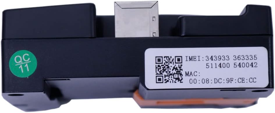
Figure 3.3: Bottom view of the module, displaying the IMEI and MAC address via QR codes and text. The IMEI is 343933363335511400540042 and MAC address is 00:08:DC:9F:CE:CC.
Port Descriptions:
- USB Device: For parameter adjustment and firmware updates.
- USB Host: For connecting external USB devices.
- ETHERNET: RJ45 port for wired internet connection to the cloud server.
- LINK: Communication port for specific genset controllers.
- RS232: Serial communication port (TX, RX, GND).
- RS485 (ISOLATION): Isolated serial communication port (A(-), B(+), SCR).
- POWER/ALARM: Power input (B+, B-) and digital input/output terminals (INPUT1, INPUT2, OUTPUT).
For software downloads and further information, scan the QR code on the module or visit http://www.smartgencloud.com/unlogin/pdadownload.
4. Setup and Installation
The CMM366A-ET module offers flexible installation options and straightforward connectivity.

Figure 4.1: Side view of the module, illustrating the integrated mounting clips for guide-rail installation.
4.1. Mounting the Module
- Guide-Rail Installation: The module is designed for standard π-type 35mm guide-rail installation. Simply align the module with the rail and snap it into place using the integrated clips.
- Screw-Fixed Installation: Alternatively, the module can be screw-fixed directly to a surface. Use appropriate screws for the mounting holes located on the module's casing.
- Ensure the module is securely mounted within the genset control box or desired location to prevent vibration and damage.
4.2. Power Connection
- Connect the power supply to the "POWER/ALARM" terminals (B+ and B-).
- The module accepts a wide DC input voltage range of 8V to 35V. It can be directly powered by the genset's built-in starter battery.
- Ensure correct polarity to prevent damage to the module.
4.3. Communication Connections
- Genset Controller Connection: Connect the module to your genset controller using one of the available ports: RS485, RS232, LINK, or USB (Host). Select the port compatible with your genset controller.
- Ethernet Connection: Connect an Ethernet cable from the module's ETHERNET port to your network router or switch to establish an internet connection. This is crucial for cloud monitoring.
- Auxiliary Digital Inputs: Connect external alarm signals to the "INPUT1" and "INPUT2" terminals if you wish to monitor additional conditions (e.g., generator room entrance, theft, fire).
- Auxiliary Relay Output: Connect devices or systems that should be triggered by an alarm to the "OUTPUT" relay terminals.
Video 4.1: An unboxing and overview of the Smartgen CMM366A-ET Cloud Monitoring Communication Module, demonstrating its physical appearance and included components.
5. Operation
Once the module is installed and connected, it can begin monitoring and transmitting data.
5.1. Cloud Server Connection and Monitoring
- Ensure the module has a stable Ethernet connection to the internet.
- The module will automatically attempt to log into the cloud server.
- Once connected, the cloud server will provide the necessary communication protocol for your specific genset controller.
- The module will then acquire genset data via the configured RS485, USB, LINK, or RS232 port.
- This data is transmitted to the cloud server, enabling real-time monitoring of the genset's running status and access to historical records via the dedicated mobile APP (iOS or Android) or PC terminal.
5.2. Alarm Functionality
- The module is configured to immediately upload data to the cloud server when an alarm condition is detected by the genset controller or via the auxiliary digital inputs.
- The auxiliary relay output can be configured to trigger external alarm devices or systems based on detected conditions.
5.3. Parameter Adjustment
- Parameters of the CMM366A-ET module can be adjusted via the USB port. Refer to the specific software provided by Smartgen for detailed instructions on parameter configuration.
6. Maintenance
To ensure optimal performance and longevity of your CMM366A-ET module, follow these maintenance guidelines:
- Regular Cleaning: Keep the module clean and free from dust and debris. Use a soft, dry cloth for cleaning. Avoid using liquid cleaners or solvents.
- Environmental Conditions: Ensure the operating environment remains within the specified temperature range (-30℃ to +70℃) and humidity levels. Avoid exposure to excessive moisture or corrosive substances.
- Connection Integrity: Periodically check all cable connections (power, communication, Ethernet) to ensure they are secure and free from corrosion or damage.
- Firmware Updates: Check the manufacturer's website (http://www.smartgencloud.com/unlogin/pdadownload) for any available firmware updates. Keeping the firmware updated can improve performance and add new features.
- Power Supply Check: Verify that the power supply voltage remains within the specified DC (8~35)V range.
7. Troubleshooting
This section provides solutions to common issues you might encounter with the CMM366A-ET module.
| Problem | Possible Cause | Solution |
|---|---|---|
| Module does not power on. | No power supply; Incorrect power connection; Power supply voltage out of range. | Check power cable connection. Ensure power supply is within DC (8~35)V. Verify correct polarity (B+ and B-). |
| Cannot connect to cloud server. | No Ethernet connection; Network configuration issue; Cloud server offline. | Verify Ethernet cable is securely connected. Check network router/switch status. Ensure internet access is available. Contact Smartgen support if cloud server issues persist. |
| No genset data displayed on APP/PC. | Incorrect communication port selection; Genset controller not powered or communicating; Incorrect protocol configuration. | Confirm the correct communication port (RS485, USB, LINK, RS232) is selected and connected. Ensure genset controller is operational. Verify communication protocol settings are correct. |
| Alarm signals not triggering. | Incorrect wiring of digital inputs/outputs; Alarm conditions not met; Module configuration error. | Check wiring for auxiliary digital inputs (INPUT1, INPUT2) and relay output (OUTPUT). Verify alarm conditions are actually occurring. Review module parameter settings for alarm triggers. |
8. Specifications
| Parameter | Value |
|---|---|
| Model Number | CMM366A-ET |
| Manufacturer | Graigar |
| Material | Plastic |
| Power Supply | DC (8~35)V |
| WIFI/Ethernet/3G/2G | Ethernet |
| Digital Input | 2 |
| Relay Output | 1 |
| RS485 | Yes |
| RS232 | Yes |
| LINK | Yes |
| USB Device | Yes |
| USB Host | Yes |
| Clock | Yes |
| Installation Method | Railway/Screw Fixing |
| Case Dimensions (mm) | 73*105*35 |
| Net Weight (kg) | 0.15 |
| Operating Temperature | (-30~+70)℃ |
9. Warranty and Support
For warranty information, technical support, or service inquiries, please contact Graigar directly or refer to the official Smartgen website.
- Official Website: For the latest documentation, software, and support resources, visit the Smartgen official website.
- Customer Service: If you encounter any issues not covered in this manual, please reach out to Graigar customer service for assistance.
Related Documents - CMM366A-ET
 |
HGM93XX MPU(CAN) Series Genset Controller User Manual | Graigar This comprehensive user manual for the Graigar HGM93XX MPU(CAN) series genset controllers provides detailed information on operation, installation, specifications, and troubleshooting. It covers models like HGM9310MPU, HGM9320MPU, HGM9310CAN, and HGM9320CAN, essential for managing automated generator systems. |
 |
SmartGen CMM366A-ET Cloud Monitoring Communication Module User Manual User manual for the SmartGen CMM366A-ET, a cloud monitoring communication module for gensets. It details features, specifications, installation, connectivity options, configuration, troubleshooting, and packing list for efficient generator monitoring. |
Ask a question about this manual
Ask about setup, troubleshooting, compatibility, parts, safety, or missing instructions. Manuals+ will review the question and use this page’s manual context to help answer it.