1. Introduction
The AITIAO SR602 is a compact and highly sensitive pyroelectric infrared motion sensor module designed for various electronic DIY projects. It detects human body movement by sensing infrared radiation, providing a high-level output signal when motion is detected. This module features low static power consumption, fast response, and ease of installation, making it suitable for applications such as body sensor lights, alarms, security systems, and automated equipment.

Figure 1: AITIAO SR602 Motion Sensor Module. This image shows a side view of the compact SR602 module with its dome-shaped sensor and three pins.
2. Specifications
- Product Name: SR-602 Pyroelectric Human Body Infrared Sensor Module
- Sensing Distance: Up to 5 meters; recommended 0-3.5 meters
- Output: High level (H=3.3V, L=0V)
- Power Supply: DC 3.3V-15V
- Quiescent Current: 20uA
- Delay Time: Adjustable (2.5 seconds to 1 hour)
- Blocking Time: 2 seconds (not adjustable)
- Trigger Mode: Repeatable trigger (factory default, not changeable)
- Dimensions: Approximately 0.59 x 0.59 x 0.79 inches (15 x 15 x 20 mm)
- Weight: Approximately 0.704 ounces (0.02 kg)

Figure 2: SR602 Module Dimensions. This image provides precise measurements of the SR602 module, showing its height, width, and sensor dome diameter.
3. Setup and Installation
The SR602 module is designed for easy integration into electronic circuits. The lens and pin headers are pre-mounted, requiring no debugging for basic operation. Ensure the power supply is within the specified range of 3.3V to 15V DC.
3.1 Pinout and Components
Identify the pins and key components on the module for correct connection:
- OUT: Signal Output (High when motion detected, Low otherwise)
- Power+: Positive power supply input (3.3V-15V)
- Power-: Ground connection
- Sensitivity Adjustment Resistor: Used to modify detection sensitivity.
- Delay Time Adjustment Resistor: Used to modify the output high-level duration.
- Photosensitive+/-: Pads for optional photosensitive element (photodiode) to enable day/night operation.
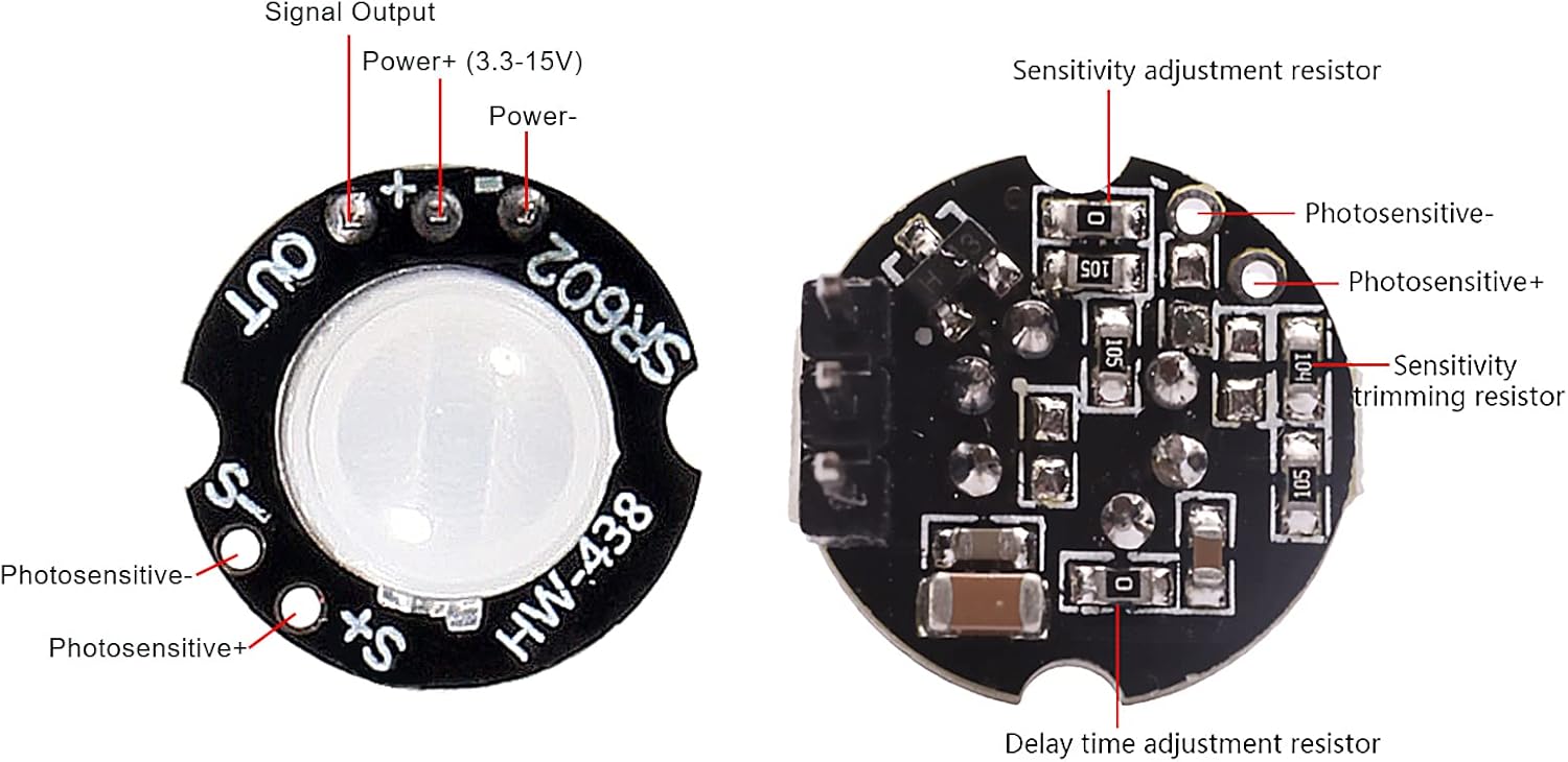
Figure 3: SR602 Module Pinout and Components. This image displays the top and bottom views of the SR602 module, clearly labeling the signal output, power connections, and adjustment resistors for sensitivity and delay time, as well as pads for an optional photosensitive element.
3.2 General Installation Guidelines
- Avoid installing the module near heat sources such as air vents, heaters, or direct sunlight, as these can cause false triggers.
- Ensure the sensor has a clear line of sight to the area where motion is to be detected.
- Mount the module securely to prevent vibrations, which could also lead to false detections.
4. Operation
Upon power-on, the module will output a high level for approximately 2 seconds, then go low and enter a standby state. This initial high-level period is part of the module's startup sequence. Once in standby, the module will detect infrared changes caused by human movement. When motion is detected, the OUT pin will go high (3.3V) for a duration determined by the delay time setting, then return to low (0V) after the delay and a 2-second blocking period.
4.1 Delay Time Adjustment
The high-level output time of this product is adjustable from 2.5 seconds to 1 hour. The default delay time is 2.5 seconds. To change the delay time, you need to modify the resistance value of the delay adjustment resistor. Refer to the table below for corresponding reference values.

Figure 4: Delay Time Adjustment Instructions Table. This table provides a reference for selecting resistor values (RL in ohms) to achieve different delay times (in seconds) for the SR602 module's output.
Note: The specified error is only a reference for the debug time range. When changing the delay time, combine it with the actual use case requirements.
4.2 Photosensitive Element (Optional)
The module has pads for an optional photosensitive element (photodiode). If a photosensitive element is installed, the module will only operate at night and remain inactive during the day. If no photosensitive components are installed (default configuration), the module will operate continuously throughout the day.
5. Circuit Connection Diagrams
Below are various examples of how to connect the SR602 module in different applications.

Figure 5: SR602 Circuit Connection Diagrams. This image illustrates five different ways to connect the SR602 module: to control a DC light bulb, to a microcontroller (MCU), through a triode control relay, through a thyristor control AC lamp circuit, and through an optocoupler control AC lamp circuit.
6. Applications
The SR602 module is versatile and can be integrated into a wide range of projects:
- Human body induction lights (e.g., hallway lights, closet lights)
- Security alarms and motion detectors
- Access control systems
- On-demand imaging systems
- Automatic equipment for agriculture, forestry, and mining
- DIY electronics projects requiring motion detection
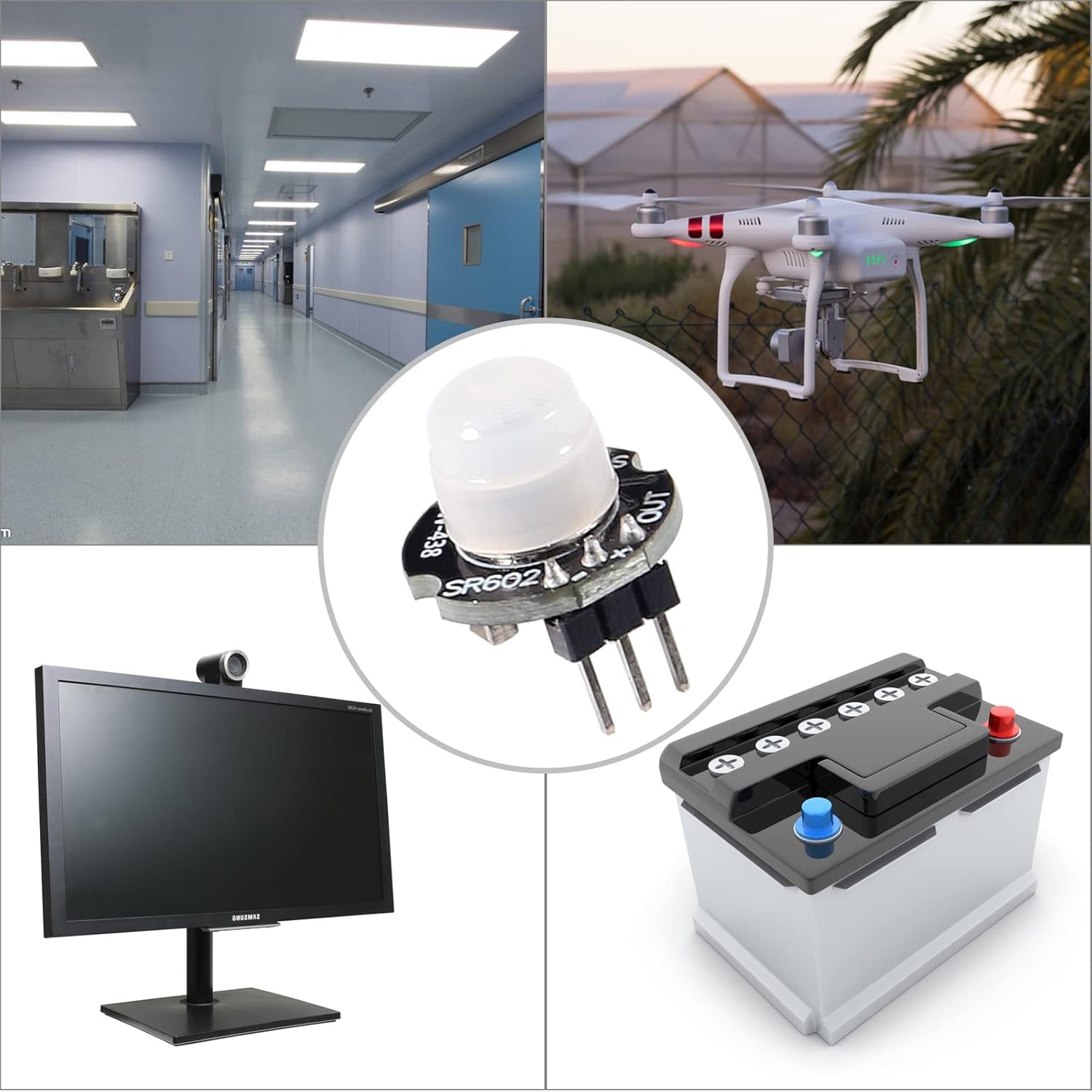
Figure 6: SR602 Application Examples. This collage shows various environments and devices where the SR602 motion sensor module can be applied, including lighting control in a hallway, drone operation, security monitoring with a display, and battery-powered systems.
7. Important Notices
- The module's supply voltage range is 3.3V to 15V. The absolute limit voltage is 2.8V to 18V. Operating outside the recommended range may damage the module.
- The blocking time is fixed at 2 seconds and cannot be adjusted. During this period after a detection, the module will not detect new motion.
- The factory default trigger mode is repeatable, meaning if motion is continuously detected during the delay time, the output will remain high until motion ceases and the delay time expires. This mode cannot be changed.
- When the delay time is changed, the initial high-level output time after power-on will also increase accordingly. This can be understood as an extended startup time before entering the normal working state.
- The module is highly sensitive. Pay close attention to the installation position and try to avoid heat source radiation (e.g., air outlets, direct sunlight) to prevent false triggers.
8. Troubleshooting
- No Detection:
- Check power supply connections and voltage (3.3V-15V).
- Ensure the sensor lens is clean and unobstructed.
- Verify the sensing distance is within the recommended range (0-3.5m).
- If using a photosensitive element, ensure ambient light conditions are appropriate for activation.
- False Triggers:
- Relocate the module away from heat sources (e.g., air conditioning vents, heating ducts, direct sunlight).
- Ensure the module is securely mounted to minimize vibrations.
- Adjust sensitivity if possible (refer to component layout for sensitivity adjustment resistor).
- Incorrect Delay Time:
- Verify the resistance value of the delay time adjustment resistor against the provided table.
- Ensure the resistor is correctly soldered and making good contact.
9. Warranty and Support
This product is covered by a standard manufacturer's warranty against defects in materials and workmanship. For technical support, troubleshooting assistance, or warranty claims, please contact your retailer or the manufacturer directly. Please have your purchase information and product model number (SR602) available when contacting support.