1. Introduction
This manual provides detailed instructions for the BORDSTRACT R503 Capacitive Fingerprint Sensor Module. It covers product features, technical specifications, installation, operation, and maintenance. The R503 sensor features a built-in algorithm chip, a 192x192 pixel sensor, and can store up to 500 fingerprints. It offers high recognition rates for various finger conditions and is suitable for integration into access control, auxiliary, and safety products.

Figure 1: BORDSTRACT R503 Fingerprint Sensor Module with multi-colored wires.
2. Key Features
- 500 Fingerprint Storage: Equipped with a built-in algorithm chip and a circular acquisition chip (192x192 pixel sensor), capable of storing up to 500 unique fingerprints.
- Professional Performance: Integrates image acquisition and algorithm processing into a single unit, ensuring reliable and professional performance.
- Sensitive Recognition: High recognition rate, adaptable to various finger conditions including dry, wet, light-print, and aged fingers.
- Wide Application: Versatile capacitive fingerprint module suitable for embedding in diverse products such as access control systems, auxiliary devices, and safes.
- Easy Installation: Designed for simple installation without the need for complex tools, featuring a small size, low power consumption, and a straightforward interface.
3. Technical Specifications
| Parameter | Value |
|---|---|
| Item Type | Fingerprint Identification Module |
| Material | Metal |
| Operating Current | 30mA (Typical Value) |
| Peak Current | 40mA |
| Fingerprint Image Entry Time | < 0.3 Seconds |
| Acquisition Window Area | Diameter: Approx. 15mm/0.6in |
| Installation Diameter | Approx.19mm/0.7in |
| Image Pixel | 192x192 Pixel |
| Image Resolution | 508dpi |
| Comparison Method | 1:1 |
| Search Mode | 1:N |
| Storage Capacity | 200pcs |
| Safety Level | Level 5 (from Low to High: 1, 2, 3, 4, 5) |
| FAR (False Acceptance Rate) | < 0.0001% |
| FRR (False Rejection Rate) | < 1.0% |
| Search Time | < 0.3 S (While 1:1000, Mean Value) |
| Upper Interface | RS232 (TTL Logic Level, 3.3v) |
| Communication Baud Rate | (9600 x N) bps, N=1-12 (default Value N=6, 57600bps) |
| Operating Temperature | -20°C to +45°C |
| Relative Humidity | 10 RH 85 RH (No Condensation) |
4. Setup & Installation
Proper setup and installation are crucial for the optimal performance of your R503 Fingerprint Sensor Module. Follow the steps below for integration.
4.1 Component Overview

Figure 2: The R503 Fingerprint Sensor Module featuring its circular capacitive surface and integrated 2-color ring indicator light.
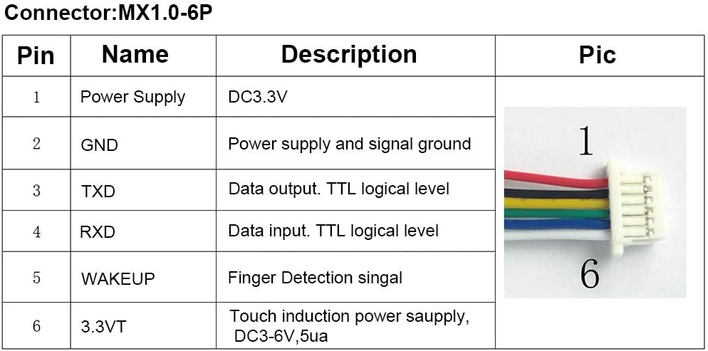

Figure 3: The R503 sensor displaying its red (left) and blue (right) ring indicator lights, which denote different operational statuses.
4.2 Wiring Diagram (MX1.0-6P Connector)
Connect the sensor to your control board using the provided MX1.0-6P connector according to the pinout table below:

Figure 4: Pinout diagram for the R503 Fingerprint Sensor Module's MX1.0-6P connector.
4.3 Physical Installation
The R503 module is designed for flush mounting. Follow these general steps:
- Drill an installation hole with a diameter of approximately 25mm (0.98 inches) in your chosen mounting surface.
- Insert the sensor module into the drilled hole from the front.
- Secure the module from the back using the threaded design and included nut.

Figure 5: Visual guide for the physical installation of the R503 Fingerprint Sensor Module.
5. Operation
The R503 Fingerprint Sensor Module operates by capturing and processing fingerprint images for identification or verification. The module's 2-color ring indicator light provides visual feedback during operation.
5.1 Fingerprint Enrollment
To enroll a new fingerprint, the module typically requires a command from the connected microcontroller or system. Once in enrollment mode, place a finger on the sensor's surface. The indicator light will change to confirm image acquisition. Multiple scans of the same finger may be required to create a robust template.
5.2 Fingerprint Verification/Identification
For verification or identification, place a registered finger on the sensor. The module will process the image and compare it against stored templates. The indicator light will signal a successful match (e.g., blue light) or a failed attempt (e.g., red light or no light).
Video 1: Demonstration of a Capacitive Fingerprint Module in operation, showing the indicator light response to finger placement for access control.
6. Maintenance
To ensure the longevity and consistent performance of your R503 Fingerprint Sensor Module, follow these maintenance guidelines:
- Cleaning: Gently wipe the sensor surface with a soft, lint-free cloth. Avoid using abrasive materials, harsh chemicals, or excessive moisture, as these can damage the sensor.
- Environmental Conditions: Operate the module within the specified temperature and humidity ranges (-20°C to +45°C, 10 RH 85 RH non-condensing) to prevent damage.
- Physical Protection: Protect the sensor from direct impact, scratches, and strong vibrations.
7. Troubleshooting
If you encounter issues with your R503 Fingerprint Sensor Module, refer to the following common problems and solutions:
- Sensor Not Responding:
- Check all wiring connections to ensure they are secure and correctly matched according to the pinout diagram.
- Verify that the power supply (DC3.3V) is stable and within the acceptable range.
- Confirm that the communication baud rate settings on your control board match the module's settings.
- Poor Recognition Rate:
- Ensure the sensor surface is clean and free from dirt, oils, or moisture.
- Instruct users to place their finger flat and centered on the sensor, covering the entire acquisition area.
- Re-enroll fingerprints if recognition issues persist, ensuring a clear and consistent finger placement during enrollment.
- Indicator Light Not Functioning:
- Check power connections.
- Verify that the control signals for the indicator light are being sent correctly from your system.
8. Warranty & Support
For warranty information, technical support, or service inquiries regarding your BORDSTRACT R503 Capacitive Fingerprint Sensor Module, please contact your retailer or the manufacturer directly. Keep your purchase receipt as proof of purchase for warranty claims.
For additional resources and updates, please refer to the official BORDSTRACT website or product page.