1. Introduction
This manual provides comprehensive instructions for the safe and efficient installation, operation, and maintenance of the WEST P6100-2110002 Temperature Controller. This device is designed for precise temperature regulation in various industrial and scientific applications, including hatching machines, featuring a two-digital display for process value (PV) and set point (SP), and an integrated alarm function.
2. Safety Information
- Electrical Safety: Ensure all wiring is performed by qualified personnel in accordance with local and national electrical codes. Disconnect power before installation or maintenance.
- Voltage: Verify that the power supply voltage matches the controller's requirements (100-240V AC, 50/60Hz).
- Environment: Install the controller in an environment free from excessive dust, moisture, corrosive gases, and vibrations.
- Proper Use: Use the controller only for its intended purpose of temperature regulation.
3. Product Overview
The WEST P6100-2110002 is a compact and reliable temperature controller. It features a clear dual-line digital display, intuitive button controls, and robust terminal connections for various inputs and outputs.

Figure 3.1: Front view of the WEST P6100-2110002 Temperature Controller, showing the dual digital display for PV and SP, and control buttons.

Figure 3.2: Side view of the controller, displaying the model number P6100 and serial number on a label.
4. Setup and Installation
Careful installation is crucial for the optimal performance and longevity of the temperature controller. Refer to the wiring diagrams and terminal descriptions below.
4.1 Mounting
The controller is designed for panel mounting. Ensure adequate space for ventilation and access to terminals.
4.2 Wiring Connections
All electrical connections must be secure and correctly terminated. Refer to the terminal block images for proper wiring.
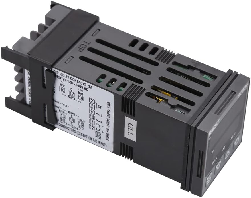
Figure 4.1: Top-down view of the controller, illustrating the wiring diagram and terminal assignments for power, inputs, and outputs.

Figure 4.2: Angled view of the terminal block, showing the screw terminals for electrical connections.

Figure 4.3: Rear view of the terminal block, providing a clear perspective of the connection points.
Power Supply:
- Connect to 100-240V AC, 50/60Hz power source.
- Power Consumption: 7.5VA.
Input:
- The controller supports various input types, including mV, mA, and Thermocouple (T/C) inputs. Refer to the specific terminal markings for correct sensor connection.
Output:
- Relay Contacts: 2A resistive at 120-240V AC. Connect heating or cooling elements to these terminals as required.
Communication:
- RS485 communication interface is available for integration with other systems.
5. Operating Instructions
The controller features a user-friendly interface for setting and monitoring temperature.
5.1 Display Indicators
- PV (Process Value): Displays the current measured temperature.
- SP (Set Point): Displays the desired target temperature.
- MAN: Indicates manual control mode.
- AT: Indicates auto-tuning is active.
- ALM: Indicates an active alarm condition.
5.2 Button Functions
- AUTO/MAN Button: Toggles between automatic and manual control modes.
- Up Arrow Button (▲): Increases the set point value or navigates menu options.
- Down Arrow Button (▼): Decreases the set point value or navigates menu options.
- Cycle/Enter Button (↻): Confirms selections, cycles through display modes, or enters parameter settings.
5.3 Setting the Temperature (Set Point)
- Press the Cycle/Enter button to access the set point adjustment mode. The SP display will flash.
- Use the Up (▲) and Down (▼) arrow buttons to adjust the SP to the desired temperature.
- Press the Cycle/Enter button again to confirm the new set point. The display will stop flashing.
5.4 Alarm Function
The ALM indicator illuminates when an alarm condition is met, as configured in the controller's parameters. Refer to the full product manual for detailed alarm setup and acknowledgment procedures.
6. Maintenance
Regular maintenance ensures the reliable operation of your WEST P6100-2110002 Temperature Controller.
- Cleaning: Periodically clean the controller's front panel with a soft, dry cloth. Do not use abrasive cleaners or solvents.
- Inspection: Regularly inspect wiring connections for tightness and signs of wear or corrosion.
- Ventilation: Ensure that ventilation openings are not obstructed to prevent overheating.
7. Troubleshooting
If you encounter issues with your temperature controller, refer to the following common problems and solutions:
| Problem | Possible Cause | Solution |
|---|---|---|
| Controller does not power on. | No power supply; incorrect wiring; blown fuse. | Check power connections; verify voltage; inspect internal fuse (if accessible and safe). |
| PV display shows 'HHHH' or 'LLLL'. | Sensor open circuit; sensor short circuit; sensor out of range. | Check sensor wiring; replace faulty sensor; ensure sensor range matches application. |
| Temperature control is unstable. | Incorrect PID parameters; sensor placement issues. | Perform auto-tuning; reposition sensor closer to the controlled area. |
| Alarm (ALM) indicator is on. | Process value exceeded alarm limits. | Check process conditions; verify alarm settings. |
If the problem persists after attempting these solutions, contact technical support.
8. Specifications
- Model: P6100-2110002
- Brand: WEST
- Display Type: LCD or LED (Dual Digital Display)
- Power Supply: 100-240V AC, 50/60Hz
- Power Consumption: 7.5VA
- Output: Relay Contacts, 2A resistive @ 120-240V AC
- Input Types: mV, mA, Thermocouple (T/C)
- Communication: RS485
- Item Weight: 1 Grams (approximately 0.035 ounces)
- Specific instructions for use: Heater control
9. Warranty and Support
For warranty information, technical support, or service inquiries, please refer to the documentation provided at the time of purchase or contact your authorized WEST distributor or reseller. Keep your purchase receipt as proof of purchase.