1. Introduction and Overview
The DIGISHUO A4988 Stepper Motor Driver Module is a complete microstepping motor driver with built-in translator for easy operation. It is designed to operate bipolar stepper motors in full, half, quarter, eighth, and sixteenth-step modes, with an output drive capacity of up to 35 V and ±2 A. The A4988 includes a fixed off-time current regulator which has the ability to operate in slow or mixed decay modes. This module is ideal for 3D printers and small CNC machines, offering precise motor control.

Image 1.1: Package contents showing five A4988 modules and five heat sinks.
2. Product Features
- Intelligent Chopping Control: Automatically selects the correct current decay mode (fast decay or slow decay).
- Integrated Protection: Features over-temperature thermal shutdown, under-voltage lockout, and crossover-current protection.
- Automatic Current Decay Mode: Detection and selection for optimal performance.
- Low Power Dissipation: Synchronous rectification for reduced energy loss.
- Logic Supply Compatibility: Compatible with both 3.3V and 5V logic supplies.
- Ground Fault Circuit: Enhanced safety features.
- Load Short-Circuit Protection: Safeguards against electrical faults.
- Multiple Step Modes: Supports full, 1/2, 1/4, 1/8, and 1/16 step resolutions.
- Value Pack: Includes 5 modules, suitable for multi-axis systems or as spares.
- Compatibility: Fully compatible with Ramps 1.4 and other common 3D printer control boards.
- Efficient Cooling: Each module includes an aluminum heat sink for effective thermal management.
- Ready-to-Use: Pre-assembled with heat sink and interface pins for immediate installation.
3. Setup and Installation
Proper installation is crucial for the reliable operation of the A4988 driver module. Follow these steps carefully:
- Attach Heat Sink: Peel off the protective film from the adhesive backing of the heat sink. Carefully align and press the heat sink onto the top of the A4988 IC chip on the module. Ensure good contact for optimal heat dissipation.
- Identify Pin Orientation: Before inserting the module into your controller board (e.g., Ramps 1.4), carefully identify the correct pin orientation. Incorrect insertion can damage the module and the controller board. Refer to your controller board's documentation for the correct orientation.
- Insert Module: Gently insert the A4988 module into the designated socket on your 3D printer controller board. Apply even pressure to ensure all pins are seated correctly.
- Connect Stepper Motor: Connect your stepper motor to the appropriate motor output pins on the controller board, ensuring the coil phases are correctly matched.
- Power Supply: Connect the appropriate power supply to your controller board. Ensure the voltage and current ratings are within the specifications of both the A4988 module and your stepper motor.

Image 3.1: A4988 module with a separate heat sink.

Image 3.2: Bottom view of the A4988 module, showing pin labels.
4. Operating Instructions
Once installed, the A4988 module requires configuration for optimal stepper motor control.
- Current Adjustment: The A4988 module has a small potentiometer (trimmer) for adjusting the motor current limit. This is crucial to prevent overheating of the motor and the driver. Use a small screwdriver to carefully turn the potentiometer while measuring the Vref voltage or the current through the motor coils (refer to A4988 datasheet for specific calculation).
- Microstepping Configuration: The A4988 supports various microstepping modes (full, 1/2, 1/4, 1/8, 1/16) controlled by the MS1, MS2, and MS3 pins. These pins are typically connected to jumpers on the controller board. Configure these jumpers according to your desired step resolution.
- Logic Voltage: The module is compatible with both 3.3V and 5V logic supplies. Ensure your controller board's logic voltage matches the module's requirements or is properly level-shifted if necessary.
- Software Control: Use your 3D printer's firmware (e.g., Marlin, Klipper) or CNC software to send step and direction signals to the A4988 module.
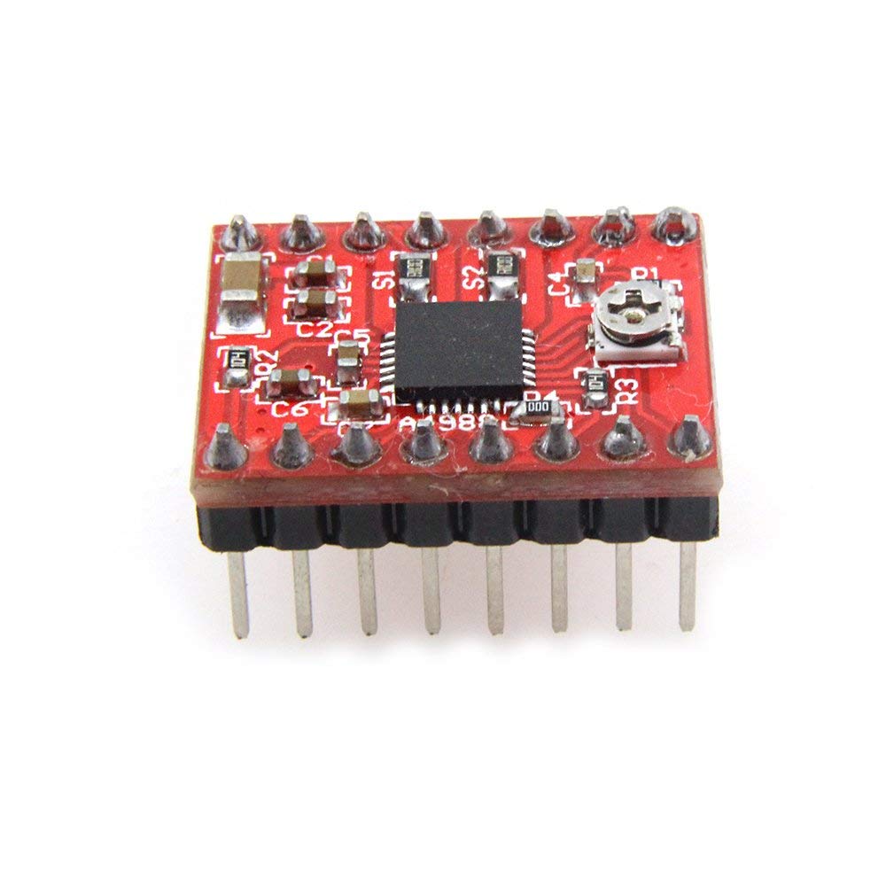
Image 4.1: Top view of the A4988 module, highlighting the current adjustment potentiometer.
5. Maintenance
To ensure the longevity and optimal performance of your A4988 driver modules, consider the following maintenance practices:
- Heat Sink Check: Periodically check that the heat sinks are securely attached and free from dust or debris that could impede heat dissipation. Clean gently with compressed air if necessary.
- Environmental Conditions: Operate the modules in a clean, dry environment with adequate ventilation to prevent overheating and dust accumulation.
- Connection Integrity: Ensure all pin connections remain firm and free from corrosion.
6. Troubleshooting
If you encounter issues with your A4988 module, consider these common troubleshooting steps:
- Motor Not Moving:
- Check power supply to the controller board and motor.
- Verify motor wiring connections.
- Ensure the module is correctly inserted into the socket.
- Confirm step and direction signals are being sent from the controller.
- Motor Overheating:
- Reduce the current limit using the potentiometer.
- Ensure the heat sink is properly attached and clean.
- Check for adequate ventilation around the module.
- Skipped Steps or Incorrect Movement:
- Verify microstepping jumper settings.
- Check for mechanical binding in the motor's load.
- Increase motor current slightly if it's too low.
- Ensure step pulse width and frequency are appropriate for the A4988.
- Module Overheating/Shutdown: The A4988 has thermal shutdown protection. If it's shutting down, it's likely due to excessive current or insufficient cooling. Review current limit, heat sink attachment, and ventilation.
7. Specifications
| Specification | Value |
|---|---|
| Model Number | A4988 |
| Dimensions (LWH) | 20 x 15 x 11 mm |
| Logic Voltage Compatibility | 3.3V and 5V |
| Step Modes | Full, 1/2, 1/4, 1/8, 1/16 |
| Protection Features | Over-temperature thermal shutdown, Under-voltage lockout, Crossover-current protection, Ground Fault Circuit, Load short-circuit protection |
| Package Contents | 5x A4988 Stepper Motor Driver Modules, 5x Heat Sinks |
8. Warranty and Support
The DIGISHUO A4988 Stepper Motor Driver Module comes with a 12-month warranty from the date of purchase. This warranty covers manufacturing defects and ensures the product meets its specified performance.
For technical support, warranty claims, or any questions regarding the product, please contact DIGISHUO customer service through the platform where the product was purchased. Please provide your order number and a detailed description of the issue to facilitate a quick resolution.