RODOT RX480E-TX118S_20SET
QIACHIP RX480E 433MHz RF Wireless Module Kit Instruction Manual
Model: RX480E-TX118S_20SET
Brand: RODOT
Product Overview
The QIACHIP RX480E 433MHz RF Wireless Transmitter and Receiver Module Kit provides a reliable solution for wireless communication in various applications. This kit includes 20 sets of high-frequency super regenerative transceiver modules and copper spring antennas, ideal for projects requiring remote control capabilities such as home security systems, electric doors, and Arduino-based projects.
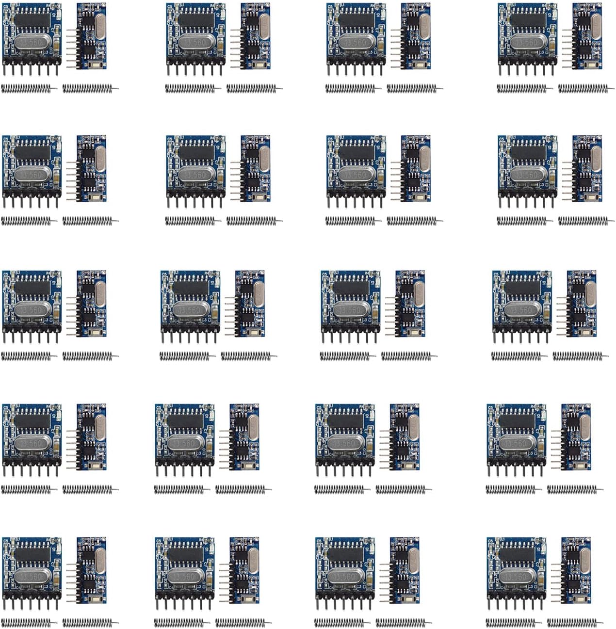
Image: Overview of the 20 sets of QIACHIP RF Wireless Transmitter and Receiver Modules with antennas.
Safety Information
Caution: This product operates on radio frequency and may interfere with other wireless devices. Handle battery with care and dispose of it responsibly. Use within the specified voltage range to avoid damage or injury.
Package Contents
- 20 x RX480E 433MHz RF Wireless Receiver Modules
- 20 x TX118S-4 433MHz RF Wireless Transmitter Modules
- 20 x RF 433MHz Copper Spring Antennas
Image: The complete kit including 20 sets of modules and antennas.
Specifications
| Feature | Specification |
|---|---|
| Brand | RODOT |
| Model | RX480E-TX118S_20SET |
| Operating Frequency | 433MHz |
| Transmitter Voltage Input | DC 3V-24V |
| Material | Copper (Antenna) |
| Item Weight | 2.39 ounces (0.07 Kilograms) |
| Package Dimensions | 6.14 x 5.12 x 1.22 inches |
Setup and Wiring
Proper wiring is crucial for the functionality of the RF modules. Refer to the diagrams below for connecting the transmitter and receiver modules to your circuit.
Transmitter (TX118S-4) Wiring

Image: Detailed wiring diagram for the TX118S-4 transmitter module.
Receiver (RX480E) Output

Image: RX480E receiver module with its 4-channel output pins labeled.
Wireless Signal Flow

Image: Diagram showing the wireless signal path from transmitter to receiver, including a ULN2003 driver chip.
Setup Demonstration Video
Video: A demonstration of setting up and testing the 433MHz RF module for remote control applications, showing the learning process and different operating modes.
Operating Modes
The receiver module supports multiple working modes, which can be set using the 'Learning Button' on the RX480E module. This button is used to set the mode and initiate the pairing process with the transmitter.

Image: Learning button and instructions for setting operating modes.
- Momentary Mode: Press the learning button once. The output is active only while the transmitter button is pressed.
- Toggle Mode: Press the learning button twice. Pressing the transmitter button once activates the output, pressing it again deactivates it.
- Latched Mode: Press the learning button three times. Pressing one transmitter button activates an output, and it remains active until another transmitter button is pressed to deactivate it.
Applications
These RF wireless modules are versatile and can be used in a wide range of applications, including:
- Remote control switches
- Motorcycle and automobile anti-theft products
- Home security systems
- Electric doors and garage door remote controls
- Remote control sockets and LED lighting
- Remote control door openers and curtains
- Alarm hosts and remote control MP3 players
Troubleshooting
If you encounter issues with your QIACHIP RF modules, consider the following common troubleshooting steps:
- Power Supply: Ensure both the transmitter and receiver modules are receiving the correct voltage within their specified ranges (DC 3V-24V for transmitter).
- Antenna Connection: Verify that the copper spring antennas are securely connected to both the transmitter and receiver modules. A properly tuned antenna is crucial for optimal range and performance.
- Pairing Process: Re-attempt the pairing process by pressing the learning button on the receiver module and then activating the transmitter. Ensure the modules are within close proximity during pairing.
- Operating Mode: Confirm that the receiver module is set to the desired operating mode (Momentary, Toggle, or Latched) as per your application requirements.
- Pin Compatibility: Be aware that the pins on the transmitter modules have a 2.0mm spacing, which is different from the standard 2.5mm spacing found on most breadboards. The pins are also shorter than standard headers. Adapters or custom wiring may be required for prototyping.
- Interference: Radio frequency interference from other wireless devices or electronic equipment can affect performance. Try operating the modules in a different environment to rule out interference.
- Range: These modules are designed for short to medium range applications. Factors like obstacles (walls, metal), power supply voltage, and antenna quality can affect the effective range.
Warranty and Support
For additional support or inquiries, please refer to the official RODOT store or contact customer service. Protection plans are available for extended coverage:
- Visit the RODOT Store
- 2-Year Protection Plan (ASIN: B082TMF6RS)
- 3-Year Protection Plan (ASIN: B082TR27NZ)
- Complete Protect (ASIN: B07RZ3LSHM)
An official Instructions for Use (IFU) document is also available in PDF format for further reference: Download IFU (PDF)
Ask a question about this manual
Ask about setup, troubleshooting, compatibility, parts, safety, or missing instructions. Manuals+ will review the question and use this page’s manual context to help answer it.