Buachois THB6128
THB6128 Motor Controller User Manual
Model: THB6128
Brand: Buachois
1. Introduction
This manual provides comprehensive instructions for the installation, operation, and maintenance of the Buachois THB6128 Motor Controller. The THB6128 is an industrial-grade DC brushless driver board module designed for precise control of stepper motors.
It features advanced chip technology with built-in temperature and overcurrent protection, ensuring reliable and stable performance. The module supports 128 subdivisions and operates within a voltage range of DC 9-36V, making it suitable for various applications in machinery manufacturing, automation equipment, and equipment maintenance.
2. Safety Information
Please read all safety instructions carefully before operating the device. Failure to follow these instructions may result in injury or damage to the product.
- Ensure the power supply voltage is within the specified range (DC 9-36V).
- Disconnect power before making any connections or disconnections.
- Avoid touching the module while it is powered on, especially the heatsink, as it may become hot.
- Install the module in a well-ventilated area to prevent overheating.
- This device is intended for use by qualified personnel.
3. Product Overview
The THB6128 Motor Controller is a compact and robust driver board. Below are key components and their functions.

Figure 3.1: THB6128 Motor Controller Module. This image shows the top view of the red PCB with blue terminal blocks on both sides, a silver heatsink, and red DIP switches.
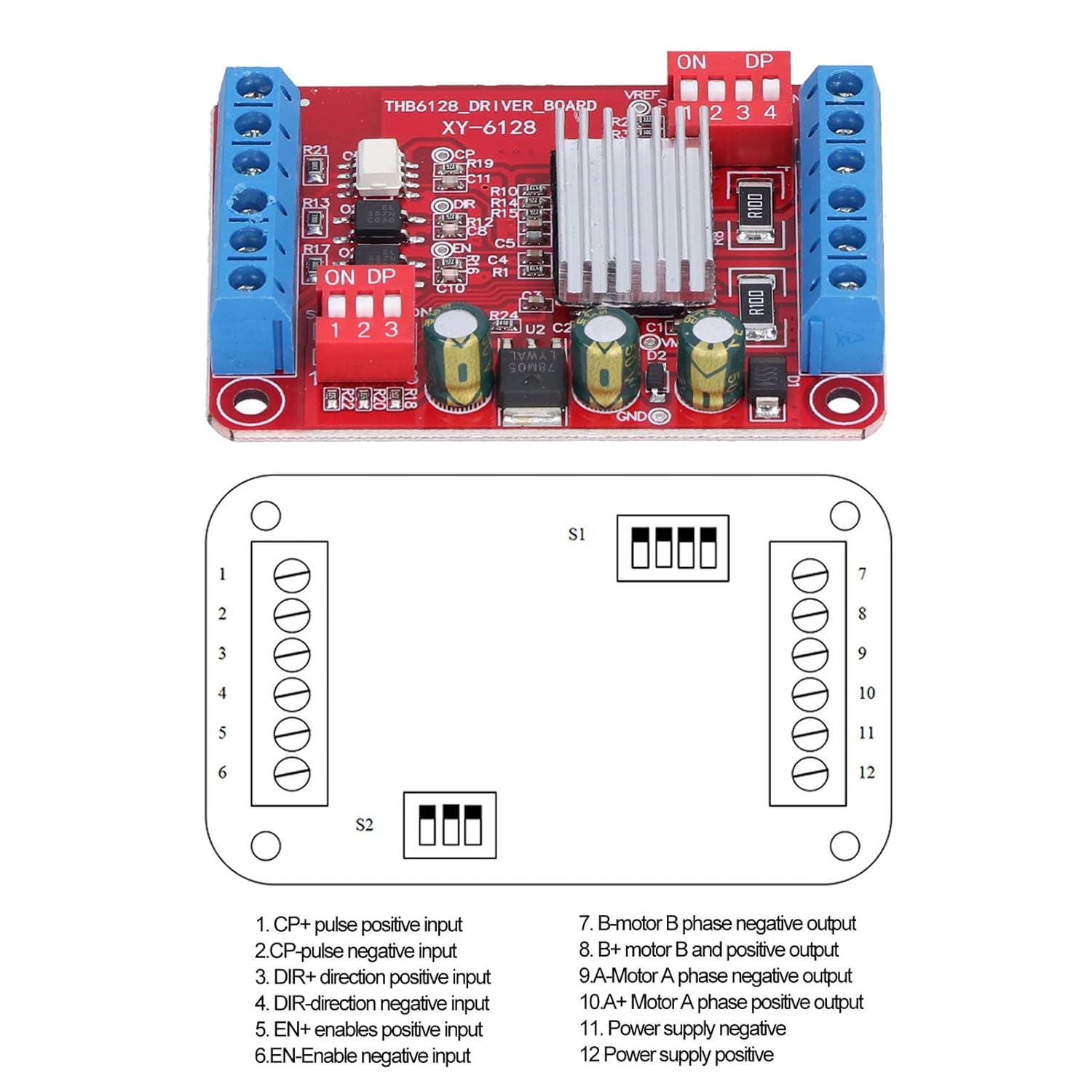
Figure 3.2: THB6128 Pinout Diagram. This diagram illustrates the connection points and their corresponding functions for the motor controller, including pulse, direction, enable, motor phase outputs, and power supply inputs.
Key features include:
- Advanced Chip: Built-in temperature and overcurrent protection, with automatic half-current locking.
- Integrated Voltage Regulator: Built-in 5V logic signal power supply voltage regulator chip with increased current-limiting resistance.
- Durable Construction: Made from high-quality PCBs, flame-retardant and shock-proof.
- Heat Sink: Includes a radiating plate for improved heat dissipation.
- Clear Markings: Reasonable wiring and clear identification for ease of use.
4. Specifications
| Parameter | Value |
|---|---|
| Model | THB6128 |
| Material | PCBs |
| Working Voltage | DC 9-36V |
| Step Subdivision | 1, 2, 4, 8, 16, 32, 64, 128 |
| Power Supply Current | 2A |
| Purpose | Drive Stepper Motor |
| Application | Stepper motor, machinery manufacturing, automatic equipment, equipment maintenance |
5. Setup
Follow these steps to set up your THB6128 Motor Controller:
- Power Connection: Connect your DC 9-36V power supply to the "VM" (positive) and "VG" (negative) terminals on the driver board. Ensure correct polarity.
- Motor Connection: Connect your stepper motor to the A+, A-, B+, B- terminals. Refer to your motor's specifications for correct phase wiring.
- Control Signal Connection:
- CP+ / CP-: Pulse signal input (positive/negative).
- DIR+ / DIR-: Direction signal input (positive/negative).
- EN+ / EN-: Enable signal input (positive/negative).
- Subdivision Setting: Adjust the DIP switches (labeled ON DP 1 2 3 4) to set the desired step subdivision. Refer to the operation section for specific settings.
- Heatsink Installation: Ensure the provided radiating plate (heatsink) is properly attached to the main chip for optimal thermal performance.
Note: Always double-check all connections before applying power to prevent damage to the module or motor.
6. Operation
The THB6128 motor controller's operation is primarily controlled by the input signals and the subdivision settings.
6.1. Subdivision Settings
The module supports various step subdivisions, which are configured using the onboard DIP switches. The switches are typically labeled 1, 2, 3, 4. Consult the specific pinout diagram (Figure 3.2) for the exact switch configuration for each subdivision setting.
| Subdivision | Switch 1 | Switch 2 | Switch 3 | Switch 4 |
|---|---|---|---|---|
| 1 (Full Step) | OFF | OFF | OFF | OFF |
| 2 | ON | OFF | OFF | OFF |
| 4 | OFF | ON | OFF | OFF |
| 8 | ON | ON | OFF | OFF |
| 16 | OFF | OFF | ON | OFF |
| 32 | ON | OFF | ON | OFF |
| 64 | OFF | ON | ON | OFF |
| 128 | ON | ON | ON | OFF |
Note: The exact mapping of DIP switches to subdivision settings may vary slightly. Always refer to the product's specific documentation or test to confirm. The table above provides a common configuration.
6.2. Control Signals
- Pulse (CP): Each pulse signal received by the CP+ / CP- inputs will cause the motor to move one step (or microstep, depending on subdivision).
- Direction (DIR): The state of the DIR+ / DIR- inputs determines the rotation direction of the motor.
- Enable (EN): When the EN+ / EN- inputs are active (typically low), the motor driver is enabled. When inactive (typically high), the motor phases are de-energized, allowing the motor shaft to be freely rotated.
7. Maintenance
The THB6128 Motor Controller is designed for durability and requires minimal maintenance. However, following these guidelines can prolong its lifespan:
- Keep the module clean and free from dust and debris. Use a soft, dry cloth for cleaning.
- Ensure proper ventilation around the module, especially the heatsink, to prevent overheating.
- Regularly check all wiring connections to ensure they are secure and free from corrosion.
- Avoid exposing the module to excessive moisture or extreme temperatures.
8. Troubleshooting
If you encounter issues with your THB6128 Motor Controller, refer to the following common problems and solutions:
- Motor Not Moving:
- Check power supply voltage (DC 9-36V) and polarity.
- Verify motor wiring (A+, A-, B+, B-).
- Ensure the Enable (EN) signal is active (low).
- Check if pulse (CP) signals are being sent correctly from your control system.
- Motor Jittering or Making Noise:
- Incorrect motor phase wiring.
- Subdivision setting might be too high for the motor or control signal frequency.
- Insufficient power supply current.
- Module Overheating:
- Ensure the heatsink is properly installed.
- Verify adequate ventilation around the module.
- Check if the motor current is within the 2A limit.
- Consider reducing the motor current or adding external cooling if operating continuously at high loads.
- Incorrect Direction:
- Check the state of the Direction (DIR) signal.
- Reverse the wiring of one of the motor phases (e.g., swap A+ and A-).
If the problem persists after trying these solutions, please contact customer support.
9. Warranty and Support
Buachois products are manufactured to high-quality standards. For warranty information and technical support, please refer to the product packaging or contact your retailer. You may also visit the official Buachois website for further assistance and resources.
For direct support, please provide your product model (THB6128) and a detailed description of the issue.
Related Documents - THB6128
 |
RRD Silencioso User Guide: Installation and Configuration Comprehensive user guide for the Reprapdiscount RRD Silencioso stepper motor driver, covering installation, wiring, and Marlin configuration for 3D printers. |