1. Product Overview
This manual provides instructions for the L-faster 500W Motor Controller, designed for brush DC motors in electric bikes and scooters. It supports multiple voltage configurations: 24V, 36V, and 48V. The controller manages motor speed and integrates various electrical components for efficient operation.
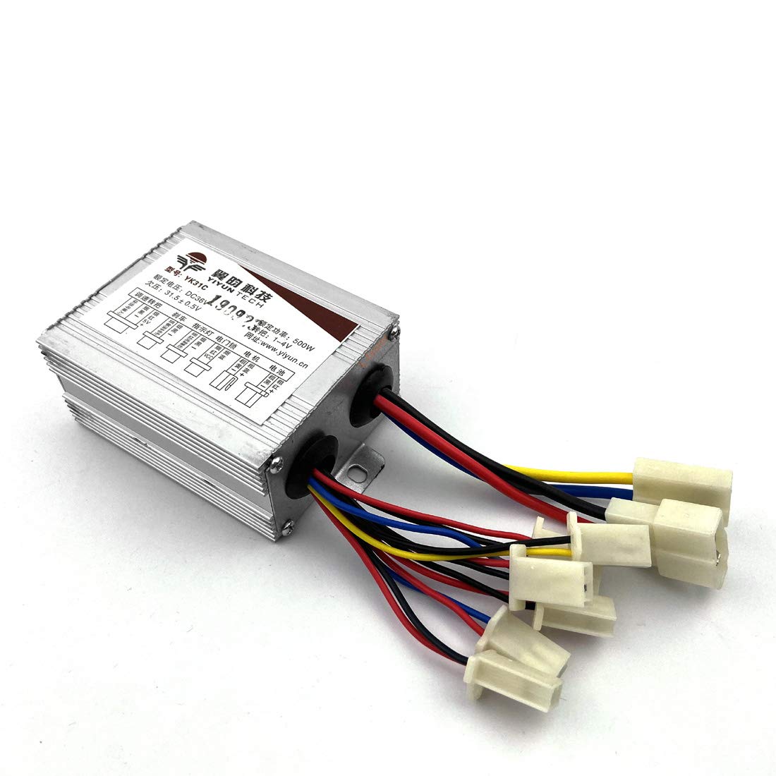
Image 1.1: Front view of the L-faster 500W Motor Controller, showing the main unit and various colored wires with white connectors.
2. Safety Information
Please read and understand all safety instructions before installation and operation. Failure to follow these instructions may result in electric shock, fire, or serious injury.
- Always disconnect power from the battery before making any electrical connections or disconnections.
- Ensure all connections are secure and properly insulated to prevent short circuits.
- Do not operate the controller if it is damaged or has exposed wiring.
- Keep the controller away from water and excessive moisture.
- Installation should be performed by individuals with adequate electrical knowledge.
3. Setup and Installation
Proper installation is crucial for the controller's performance and safety. Refer to the wiring diagram and connector labels carefully.

Image 3.1: Detailed wiring diagram illustrating the various connectors and their functions on the L-faster 500W Motor Controller.
3.1 Wiring Connections
- Battery Connection: Connect the main power wires from your battery pack to the designated battery input on the controller. Ensure correct polarity (red to positive, black to negative).
- Motor Connection: Connect the motor wires to the motor output on the controller. For brushed motors, typically two main wires (often blue and yellow) connect directly.
- Power Lock: Connect the power lock (ignition switch) wires. This typically enables or disables power to the controller.
- Throttle: Connect the throttle wires. This usually involves three wires: power, ground, and signal.
- Brake Light: Connect the brake light wires. This activates the brake light when the brakes are applied.
- Charging Port: Connect the charging port wires, if applicable, to allow for external battery charging without disconnecting the controller.
- Light: Connect any auxiliary light wires to the designated light output.
- Brake Lever: Connect the brake lever wires. This provides a signal to the controller to cut motor power when brakes are engaged.
3.2 Mounting the Controller
Mount the controller in a secure location, protected from physical damage, water, and excessive heat. Ensure adequate airflow around the unit for cooling. The controller dimensions are approximately 83mm x 65mm x 42mm.

Image 3.2: Physical dimensions of the L-faster 500W Motor Controller for mounting reference.
4. Operating Instructions
Once all connections are securely made and verified, you can begin operating your electric vehicle.
- Turn on the power lock (if installed).
- Gently apply the throttle to initiate motor movement. The controller will regulate the motor speed based on throttle input.
- Apply brakes as needed. The controller is designed to cut motor power when the brake levers are activated.
- Monitor battery levels and charge as necessary via the charging port.
5. Maintenance
Regular maintenance ensures the longevity and reliable performance of your motor controller.
- Periodically inspect all wiring connections for looseness or corrosion.
- Keep the controller clean and free from dust, dirt, and debris.
- Ensure the controller is not exposed to extreme temperatures or direct sunlight for prolonged periods.
- Check for any signs of physical damage to the controller casing or wires.
6. Troubleshooting
If you encounter issues, refer to the following common troubleshooting steps:
| Problem | Possible Cause | Solution |
|---|---|---|
| Motor not running | No power to controller, loose connections, faulty throttle, engaged brake lever. | Check battery connection, verify power lock is on, inspect all wiring, test throttle, ensure brake levers are not engaged. |
| Intermittent power | Loose wiring, poor contact in connectors. | Secure all connections, especially battery and motor wires. |
| Overheating controller | Excessive load, insufficient ventilation, short circuit. | Reduce load, ensure proper airflow around controller, check for short circuits. |
If problems persist after attempting these solutions, contact customer support.
7. Specifications
- Brand: L-faster
- Model: 500W
- Supported Voltages: 24V, 36V, 48V
- Item Package Dimensions: 8.66 x 3.35 x 2.01 inches
- Package Weight: 0.19 Kilograms
- First Available Date: October 14, 2021
8. Product Video
Watch this official product video for a visual overview of the L-faster 500W Motor Controller.
Video 8.1: An 18-second video demonstrating the L-faster 24V 36V 48V 500W Electric Motor Controller, showcasing its physical appearance and various wire connections.
9. Warranty and Support
This product comes with a standard manufacturer's warranty. For warranty claims, technical support, or further assistance, please contact the seller or manufacturer directly. Keep your purchase receipt for proof of purchase.
Manufacturer: L-faster