1. Introduction
This manual provides essential information for the safe and efficient operation, installation, and maintenance of your sloHEXtted Q800 8-Button Industrial Wireless Crane Remote Control System. Please read this manual thoroughly before installation and operation to ensure proper usage and to prevent potential hazards.

Figure 1.1: sloHEXtted Q800 Wireless Crane Remote Control System (Transmitter and Receiver)
2. Product Features
- 8-Button Momentary Control: The system features an 8-button transmitter designed for momentary operation, suitable for various crane and hoist functions.
- Wide Voltage Compatibility: The receiver supports 110-460V AC/DC power input, ensuring versatility across different industrial setups.
- Extended Control Range: Offers a control distance of up to 100 meters with 360-degree barrier-free remote control and strong signal penetration.
- Durable Construction: Both the transmitter and receiver are constructed from PA65 reinforced flame-retardant fiber plastic, providing strong anti-pressure ability, waterproofing, anti-corrosion properties, and insulation.
- Ergonomic Transmitter Design: The lightweight transmitter features an ergonomic design for comfortable handling during extended use.
- IP65 Rated Protection: The system complies with IP65/NEMA4 international specifications, making it dust-proof and waterproof, suitable for harsh environments with oil pollution, high humidity, and dust.
- High-Quality Components: Equipped with a quality circuit board for reliable performance, dust-proof structure, and high-performance metal contact buttons.
- Emergency Stop Function: An EU standard emergency stop push button is integrated on the transmitter for immediate system shutdown in critical situations.
- Silicone Buttons: Durable silicone-wrapped buttons enhance comfort and tactile feedback.
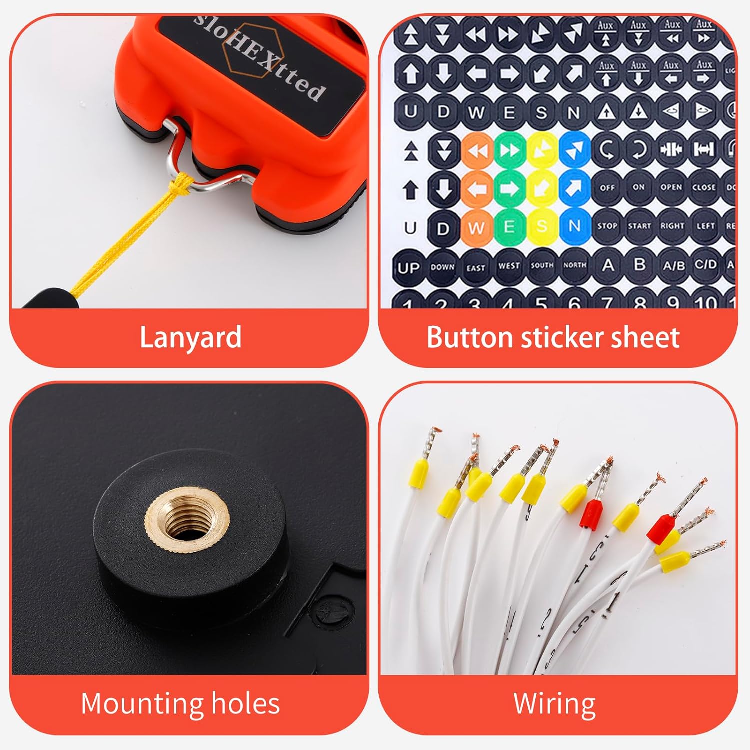
Figure 2.1: Transmitter with key components labeled, including Emergency Stop, ON/HORN, Status LED, and Silicone Buttons.

Figure 2.2: Close-up view of the EU Standard Emergency Stop button, designed for quick and safe operation.

Figure 2.3: The transmitter housing, made from nylon reinforced fiber plastic, provides shock-proof protection.
3. Setup and Installation
3.1 Unpacking and Inspection
Upon receiving your Q800 system, carefully unpack all components and inspect them for any signs of damage. Ensure all listed components are present:
- Transmitter
- Receiver
- Transmitter dust-cover
- Button sticker sheet
- Mounting hardware (bolts, washers, spring)

Figure 3.1: Included components: Lanyard, Button Sticker Sheet, Mounting Holes on receiver, and pre-wired connections.
3.2 Power Supply and Wiring
The receiver requires a power supply within the 110-460V AC/DC range. It is crucial to select the correct voltage according to the voltage marked on the contactor in the control box of your crane or hoist. Incorrect voltage can cause severe damage to the unit and connected equipment.
- Identify Power Source: Locate the main power source for your crane or hoist control box.
- Verify Voltage: Confirm the voltage of the power source matches the receiver's specifications (110-460V AC/DC).
- Connect Wiring: Connect the receiver's pre-wired cables to the corresponding terminals in your control box. Refer to the wiring diagram provided on the receiver unit for precise connections. Ensure all connections are secure and insulated.
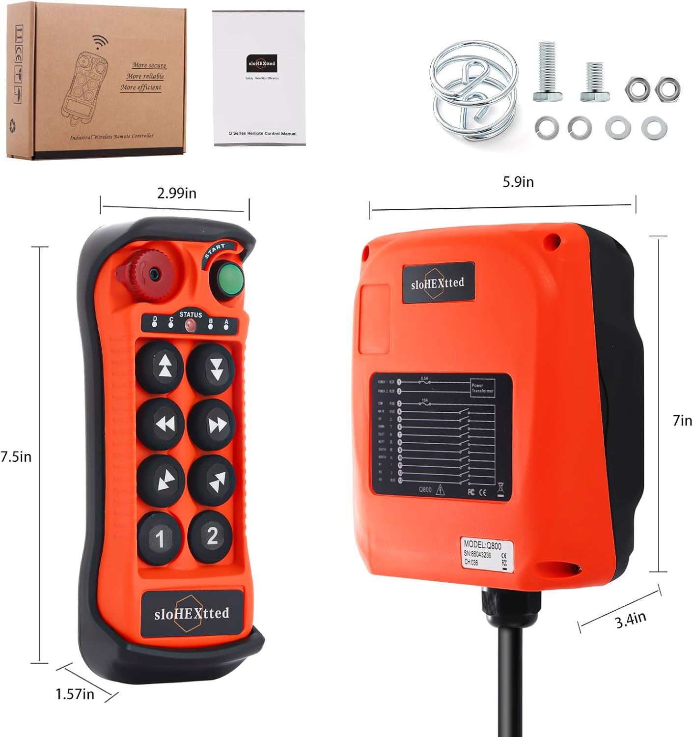
Figure 3.2: The receiver unit displays a clear wiring diagram for proper electrical connections.
3.3 Receiver Mounting
The receiver unit should be mounted in a secure location, protected from excessive vibration and direct impact. Use the provided mounting holes and hardware for installation.
- Select Location: Choose a mounting location that allows for optimal signal reception and easy access for wiring.
- Secure Receiver: Use appropriate bolts, washers, and nuts to firmly attach the receiver to a stable surface.
3.4 Transmitter Battery Installation
The transmitter requires batteries for operation. Batteries are not included with the system and must be purchased separately. Refer to the transmitter's battery compartment for the correct battery type and orientation.
4. Operating Instructions
4.1 Basic Operation
The Q800 system operates as a momentary control system. Functions are active only while the corresponding button is pressed.
- Power On: Press the green 'START' button to activate the transmitter. The status LED will indicate power.
- Function Buttons: Use the directional buttons (Up, Down, East, West, South, North) and auxiliary buttons (1, 2) to control the corresponding functions of your crane or hoist.
- ON/HORN Button: Press the 'ON/HORN' button for signaling or activating an auxiliary function.
- Emergency Stop: In case of an emergency, press the red 'Emergency Stop' button to immediately halt all operations. To reset, twist the button clockwise and pull it out.
Video 4.1: This video demonstrates the secure and efficient operation of the Q800 crane remote control, highlighting its responsiveness and ease of use.
Video 4.2: This video illustrates the functionality of the hoist crane industrial wireless remote transmitter and receiver, showcasing its application in industrial settings.
5. Maintenance
5.1 Cleaning
Due to its IP65 rating, the system is resistant to dust and water. However, regular cleaning is recommended to maintain optimal performance and longevity.
- Wipe down the transmitter and receiver with a damp cloth to remove dirt and grime.
- Avoid using harsh chemicals or abrasive cleaners that could damage the plastic housing or silicone buttons.
- Ensure the emergency stop button is free from debris to allow for proper function.
5.2 Battery Replacement
When the transmitter's battery indicator shows low power, replace the batteries promptly to avoid interruption of operation. Refer to the transmitter's battery compartment for instructions on how to open it and replace the batteries correctly.
5.3 General Inspection
Periodically inspect the system for any signs of wear, damage, or loose connections. Pay attention to:
- The integrity of the transmitter's silicone shell and buttons.
- The receiver's housing for cracks or damage.
- All wiring connections to ensure they are tight and free from corrosion.
6. Troubleshooting
This section provides basic troubleshooting steps for common issues. For more complex problems, contact customer support.
| Problem | Possible Cause | Solution |
|---|---|---|
| System not responding | Low transmitter battery Emergency Stop engaged Receiver not powered Out of range | Replace transmitter batteries Disengage Emergency Stop Check receiver power supply Move closer to the receiver |
| Intermittent control | Signal interference Loose wiring connection | Relocate receiver or transmitter to avoid interference Check and secure all wiring connections |
| Buttons unresponsive | Damaged button Internal fault | Inspect buttons for physical damage Contact customer support |
7. Technical Specifications
| Specification | Detail |
|---|---|
| Manufacturer | sloHEXtted |
| Part Number | Q800 |
| Item Model Number | Q800 8-Button 110-460V AC/DC |
| Item Weight | 4.27 pounds |
| Product Dimensions | 5 x 3 x 2 inches |
| Receiver Voltage | 110-460V AC/DC |
| Control Type | Momentary Push Button |
| Handle/Lever Placement | Push Button |
| Material | PA65 Reinforced Flame Retardant Fiber Plastic |
| IP Rating | IP65 / NEMA4 |
| Control Distance | Up to 100 meters |
| Batteries Included | No |
| Batteries Required | Yes |
| Included Components | Transmitter, Receiver, Transmitter Dust-Cover, Button Sticker Sheet |
8. Warranty and Support
8.1 Warranty Information
For specific warranty details regarding your sloHEXtted Q800 system, please refer to the warranty card included with your product or contact the manufacturer directly. Keep your proof of purchase for any warranty claims.
8.2 Customer Support
If you encounter any issues not covered in this manual or require further assistance, please contact sloHEXtted LLC customer support. Contact information can typically be found on the product packaging or the official sloHEXtted website.


