1. Introduction
The MustOOL MT336 is a versatile 2-in-1 True RMS Digital Clamp Meter and Oscilloscope. This device allows for non-contact measurement of AC current waveforms, DC/AC voltage, resistance, capacitance, frequency, and temperature. It features a waveform display for quick analysis and includes functions like diode testing and continuity checks. Designed for safety and efficiency, it is an essential tool for electrical measurements.
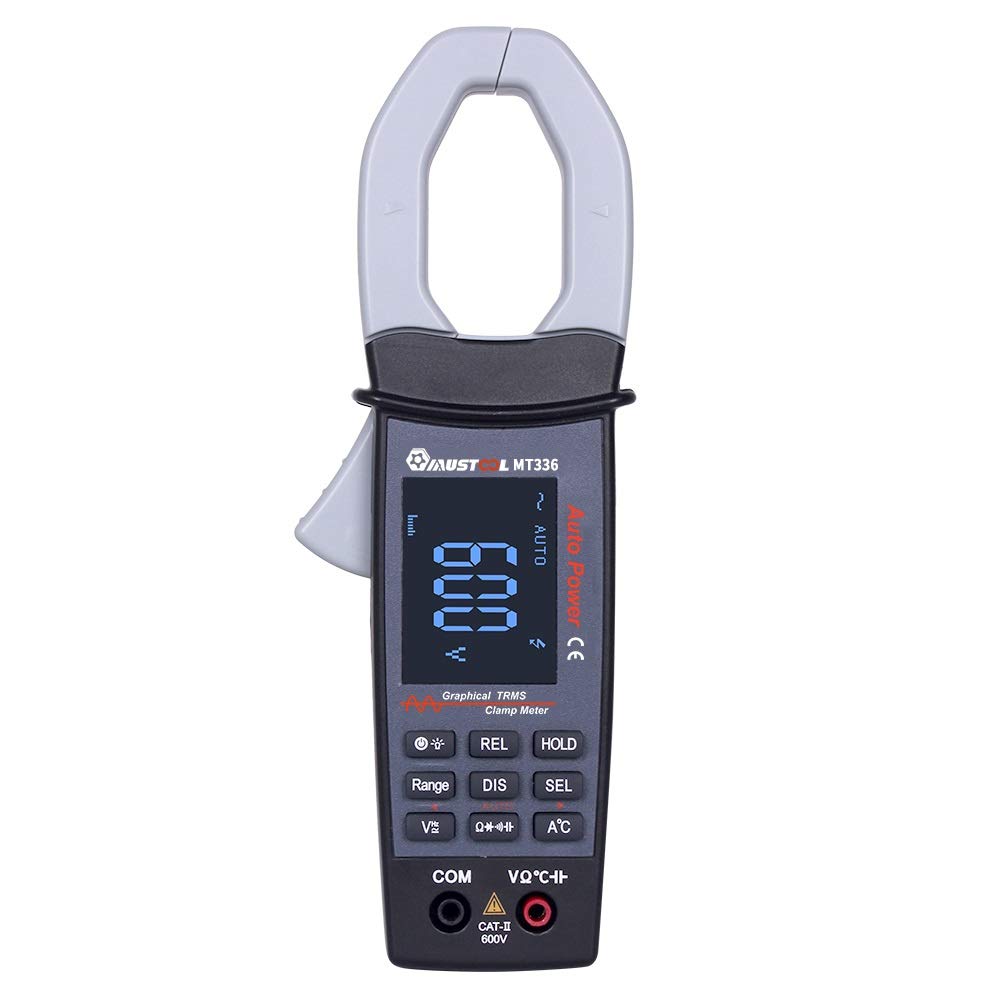
Figure 1: MustOOL MT336 Digital Clamp Meter in use, showing its display.
2. Safety Information
Always adhere to safety precautions when using electrical testing equipment. Failure to do so may result in electric shock, injury, or damage to the meter or equipment under test.
- Do not exceed the maximum input limits for any function.
- Ensure the test leads are in good condition and properly connected before use.
- Do not use the meter if it appears damaged or if the battery cover is not properly closed.
- Exercise extreme caution when working with voltages above 60V DC or 30V AC RMS.
- Always disconnect power to the circuit before making resistance, capacitance, or diode measurements.
- Remove test leads from the meter before opening the battery compartment.

Figure 2: Rear view of the MT336, highlighting safety warnings and battery information.
3. Product Components
The MustOOL MT336 clamp meter includes the following main components:
- Clamp Jaw: For non-contact AC current measurement.
- Trigger: Opens and closes the clamp jaw.
- LCD Display: Shows measurement readings, waveforms, and function indicators.
- Function Buttons: For selecting modes, ranges, and other features.
- Input Jacks (COM, VΩHz): For connecting test leads for voltage, resistance, capacitance, frequency, diode, and continuity measurements.
- Temperature Probe Input: For connecting the included temperature probe.
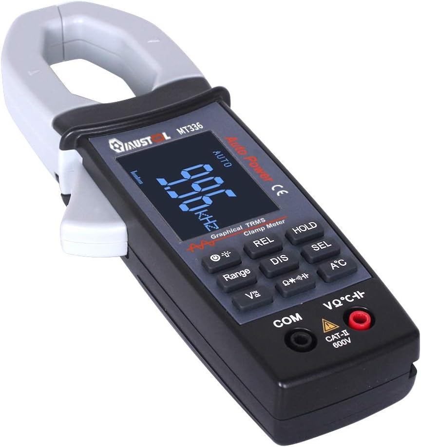
Figure 3: Overview of the MT336 clamp meter, showing its main parts.
4. Setup
4.1 Battery Installation
- Ensure the meter is powered off and no test leads are connected.
- Locate the battery compartment on the back of the meter.
- Unscrew the battery compartment cover.
- Insert three AAA 1.5V batteries, observing correct polarity.
- Replace the battery compartment cover and secure it with the screw.
4.2 Connecting Test Leads
For voltage, resistance, capacitance, frequency, diode, and continuity measurements:
- Insert the black test lead into the COM (Common) input jack.
- Insert the red test lead into the VΩHz input jack.
For temperature measurements, connect the temperature probe to the designated input ports.
5. Operating Instructions
5.1 Power On/Off
Press the power button to turn the meter on. The meter will automatically shut down after 15 minutes of inactivity to conserve battery life. Press the power button again to turn it off manually.
5.2 AC Current Measurement (Clamp Function)
- Select the AC current mode (usually indicated by 'A~' or a similar symbol).
- Press the trigger to open the clamp jaw.
- Enclose a single conductor (not a power cord with multiple wires) within the clamp jaw.
- Release the trigger to close the jaw securely around the conductor.
- Read the AC current value and waveform on the display.

Figure 4: Measuring AC current and waveform using the clamp function.
5.3 AC/DC Voltage Measurement
- Connect the test leads as described in Section 4.2.
- Select the appropriate voltage mode (DCV or ACV).
- Touch the red and black test probes to the points where voltage is to be measured.
- Read the voltage value on the display. For AC voltage, the waveform may also be displayed.

Figure 5: Measuring AC voltage and waveform from a power outlet.
5.4 Resistance, Capacitance, Frequency, Diode, and Continuity
For these functions, ensure the circuit is de-energized before connecting the test leads. Select the desired function using the mode buttons and follow standard measurement procedures for multimeters.
- Resistance (Ω): Measures the electrical resistance of a component.
- Capacitance (F): Measures the capacitance of capacitors.
- Frequency (Hz): Measures the frequency of an AC signal.
- Diode Test: Checks the forward voltage drop of a diode.
- Continuity Test: Indicates if a circuit is complete with a low resistance path (typically with an audible beep).
5.5 Temperature Measurement
Connect the temperature probe to the meter's designated input. Select the temperature function and place the probe tip on the object or area to be measured. The temperature will be displayed in Celsius or Fahrenheit.
6. Maintenance
6.1 Cleaning
Wipe the meter with a dry, soft cloth. Do not use abrasives or solvents. Keep the input terminals free of dirt and moisture.
6.2 Battery Replacement
When the low battery indicator appears on the display, replace the batteries as described in Section 4.1. Use three new AAA 1.5V batteries.
6.3 Storage
If the meter is not used for an extended period, remove the batteries to prevent leakage and damage. Store the meter in a cool, dry place away from direct sunlight.
7. Troubleshooting
| Problem | Possible Cause | Solution |
|---|---|---|
| Meter does not power on. | Dead or incorrectly installed batteries. | Replace batteries, ensuring correct polarity. |
| No reading or "OL" displayed. | Open circuit, out of range, or incorrect function selected. | Check connections, select appropriate range/function, or ensure circuit is closed. |
| Inaccurate readings. | Low battery, dirty test leads/terminals, or external interference. | Replace batteries, clean leads/terminals, move away from strong electromagnetic fields. |
| Waveform not displayed correctly. | Signal frequency too high/low, or incorrect range. | Ensure signal is within 1kHz ACV/ACA. Adjust range if available. |
8. Specifications
General Specifications:
- Display: 128 x 64 LCM with white backlight on black screen (45mm x 35mm)
- Power: 3 x AAA 1.5V batteries
- Auto Shutdown: Approximately 15 minutes of inactivity
- Data Storage: 100 data points, 10 waveforms
- Dimensions: 78mm x 210mm x 36mm
- Weight: 220g (without batteries)
- Operating Environment: 0°C to 40°C; <75% RH
- Storage Environment: -10°C to 60°C; <90% RH
- Safety Rating: CAT II 600V
Measurement Specifications (Accuracy ±(rdg + dgt)):
| Function | Range | Accuracy |
|---|---|---|
| DC Voltage | 400mV / 4V / 40V / 400V / 600V | ±(1.5% + 10) |
| AC Voltage (TRMS) | 4V / 40V / 400V / 600V | ±(2.0% + 10) |
| AC Current | 40A / 400A | ±(2.5% + 10) |
| Resistance | 400Ω / 4kΩ / 40kΩ / 400kΩ / 4MΩ / 40MΩ | ±(1.0% + 5) |
| Capacitance | 4nF / 40nF / 400nF / 4uF / 400uF / 4mF | ±(4.0% + 10) |
| Frequency | 9.999Hz to 30kHz | ±(2.0% + 10) |
| Temperature | -20℃ to 250℃ | ±(2.0% + 3) |
| Diode Test | Open circuit voltage approx. 3V, max test current approx. 2mA | N/A |
| Continuity Test | Judgment resistance approx. 50Ω | N/A |
| Analog Bandwidth | ACV / ACA 1 kHz | N/A |
9. Warranty and Support
For warranty information and technical support, please refer to the official MustOOL website or contact your retailer. Keep your purchase receipt as proof of purchase.
The package includes: 1x Clamp Meter, 1x Pair of Test Leads, 1x English User Manual, 1x Temperature Probe.