1. Introduction
This manual provides detailed instructions for the DIYElectronic STM32H750VBT6 Development Board. This board is designed for embedded system development, featuring an ARM STM32H750VBT6 microcontroller. It includes various onboard peripherals and interfaces to facilitate rapid prototyping and project development.
Please read this manual thoroughly before operating the device to ensure proper functionality and to prevent damage.
2. Product Features
- Integrated CH340 download chip for direct code programming.
- Two onboard LED indicators.
- Four independent user-programmable buttons.
- Dedicated interface for OLED/LCD displays.
- Onboard 8MHz crystal oscillator for system clock.
- Power indicator LED.
- Onboard AT24C02 EEPROM for non-volatile data storage.
- Onboard 16M bit SPI FLASH memory.
- Integrated reset circuit.
- All microcontroller pins are exposed for flexible connectivity.
3. Package Contents
Verify that all items listed below are included in your package:
- 1x STM32H750VBT6 Development Board
- 1x USB Cable (75mm)
- 2x 22-Pin Male Headers
- 1x 11-Pin Female Header
- 1x 4-Pin Male Header
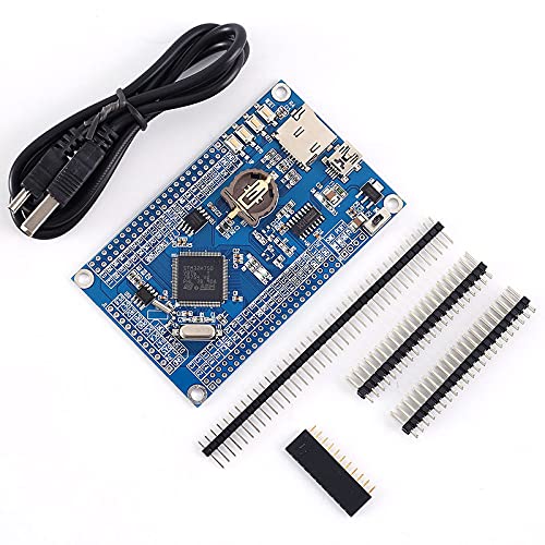
Image 3.1: STM32H750VBT6 Development Board with USB cable and various pin headers, representing the complete package contents.
4. Board Layout and Components
Familiarize yourself with the layout of the development board and its key components:

Image 4.1: Top-down view of the STM32H750VBT6 Development Board with labels indicating key components such as the STM32H750VBT6 MCU, USB to UART chip, SWD download interface, GPIO pins, OLED/LCD interface, Micro SD card socket, reset button, battery socket, EEPROM, and SPI FLASH.
- MCU (STM32H750VBT6): The main microcontroller unit, an ARM Cortex-M7 processor.
- SWD Download Interface: Serial Wire Debug interface for programming and debugging the MCU.
- USB to UART Chip (CH340): Facilitates communication and code download via the USB port.
- GPIO Pins: General Purpose Input/Output pins for connecting external components and expanding functionality.
- OLED/LCD Interface: Dedicated header for connecting compatible OLED or LCD display modules.
- Micro SD Card Socket: For external data storage, allowing for larger data logging or file systems.
- Reset Button: To restart the microcontroller and execute the loaded program from the beginning.
- CR1220 Battery Socket: For Real-Time Clock (RTC) backup power, maintaining time and date when main power is off.
- EEPROM (AT24C02): Electrically Erasable Programmable Read-Only Memory for non-volatile data storage.
- SPI FLASH (16M bit): Serial Peripheral Interface Flash memory for additional program or data storage.
- Voltage Regulator: Provides stable 3.3V power to the board components.
- Power ON/OFF: Switch to control the main power supply to the board.
- System Clock Crystal: Provides the main clock signal for the MCU's operation.
5. Setup Instructions
- Power Connection: Connect the provided USB cable to the board's USB port and to a computer or a 5V power adapter. The power indicator LED should illuminate, indicating the board is receiving power.
- Driver Installation: If using the board for the first time, your operating system may require drivers for the CH340 USB to UART chip. These drivers are typically available from the chip manufacturer's website or common driver repositories. Install them before proceeding.
- Development Environment Setup: Install a suitable Integrated Development Environment (IDE) for STM32 microcontrollers, such as STM32CubeIDE, Keil MDK, or IAR Embedded Workbench. Ensure the necessary toolchains and debuggers are configured according to the IDE's documentation.
- Connecting Peripherals: If you plan to use external components (e.g., OLED/LCD, sensors), connect them to the appropriate GPIO pins or dedicated interfaces as per your project requirements. Refer to the board layout (Image 4.1) for pin identification and consult the STM32H750VBT6 datasheet for pin functions.
- RTC Battery Installation (Optional): For Real-Time Clock functionality, insert a CR1220 coin cell battery into the designated battery socket. Ensure correct polarity (+ side up) to prevent damage and ensure proper timekeeping.
6. Operating Instructions
- Programming the MCU:
- Via USB (UART Bootloader): The onboard CH340 chip allows direct code download. Use a serial bootloader utility (e.g., STM32CubeProgrammer) to flash your compiled firmware through the USB connection.
- Via SWD (ST-Link/J-Link): For more advanced debugging and programming, connect an external SWD debugger (e.g., ST-Link V2/V3, J-Link) to the SWD download interface on the board. Configure your IDE to use this debugger for flashing and real-time debugging.
- Using GPIO Pins: Configure the GPIO pins in your firmware to control external devices or read sensor inputs. Refer to the STM32H750VBT6 datasheet and reference manual for detailed pin configurations, alternate functions, and electrical characteristics.
- Interacting with Onboard Peripherals:
- LEDs: The two onboard LEDs can be controlled via specific GPIO pins. Consult board schematics or example code for exact pin assignments.
- Buttons: The four independent buttons are connected to GPIO pins and can be used as inputs for user interaction. Implement debouncing in your software for reliable input.
- EEPROM/SPI FLASH: Utilize the appropriate communication protocols (I2C for EEPROM, SPI for FLASH) in your code to read from and write to these memory modules. Libraries are often available for these peripherals.
- Micro SD Card: Implement an SD card library in your firmware to access and manage files on an inserted Micro SD card. Ensure proper initialization and file system handling.
- Resetting the Board: Press the onboard reset button to restart the microcontroller and execute the loaded program from the beginning. This is useful for re-initializing your application.
7. Maintenance
- Cleaning: Keep the board clean and free from dust and debris. Use a soft, dry brush or compressed air for cleaning. Avoid using liquids or abrasive materials that could damage components.
- Storage: Store the development board in an anti-static bag when not in use to protect it from electrostatic discharge (ESD), which can damage sensitive electronic components.
- Environmental Conditions: Operate and store the board within the specified operating temperature (-20℃ to 85℃) and humidity (5% to 95% RH) ranges to ensure longevity and reliable performance.
- Firmware Updates: Regularly check for updated firmware libraries and development tools from STMicroelectronics or the community to benefit from bug fixes, performance improvements, and new features.
- Battery Replacement: If using the RTC battery, replace the CR1220 coin cell when its voltage drops to maintain accurate timekeeping. A low battery can lead to loss of time and date settings.
8. Troubleshooting
- Board Not Powering On:
- Ensure the USB cable is securely connected to both the board and the power source.
- Verify the power source (computer USB port or adapter) is functional and providing sufficient power.
- Check the power ON/OFF switch on the board, if present, to ensure it is in the 'ON' position.
- Unable to Upload Code:
- Confirm that the CH340 drivers are correctly installed on your computer and the device is recognized in Device Manager.
- Ensure the correct COM port is selected in your programming software (e.g., STM32CubeProgrammer).
- Verify that the board is in bootloader mode if required by your programming method (e.g., by setting specific boot pins).
- If using an external debugger (SWD), ensure it is properly connected to the SWD interface and recognized by your IDE.
- Peripherals Not Responding:
- Double-check all wiring connections to external components for correctness and secure contact.
- Review your firmware code for correct pin assignments, peripheral initialization, and communication protocols.
- Ensure the external components themselves are functional by testing them independently if possible.
- Unexpected Behavior:
- Perform a hard reset using the onboard reset button to clear any transient states.
- Re-flash a known working example program or a simple blinky LED program to isolate software issues from hardware problems.
- Consult online forums and documentation for the STM32H7 series for common issues and solutions, as well as community support.
9. Specifications
| Parameter | Value |
|---|---|
| Controller IC | STM32H750VBT6 |
| Operating Voltage | 3.3V |
| Output Voltage | 3.3V / 5V |
| Operating Temperature | -20℃ to 85℃ |
| Operating Humidity | 5% to 95% RH |
| Module Size (L x W x H) | 90mm x 55mm x 11mm (3.54 x 2.17 x 0.43 inches) |
| USB Cable Length | 75mm |
| Onboard EEPROM | AT24C02 |
| Onboard SPI FLASH | 16M bit |
| Connectivity Technology | USB |
| Operating System Compatibility | Linux (and other OS with appropriate drivers) |

Image 9.1: Diagram showing the physical dimensions of the STM32H750VBT6 Development Board: 90mm length, 55mm width, and 11mm height.
10. Warranty and Support
For warranty information and technical support, please refer to the official DIYElectronic website or contact your retailer. Keep your purchase receipt as proof of purchase.
Online resources and community forums for STM32 microcontrollers are also valuable sources for additional support, example projects, and troubleshooting tips.