1. Introduction
This manual provides essential information for the safe and efficient installation, operation, and maintenance of DAVITU Motor Driver Controller Boards. These boards are designed to control various slide gate motors, offering reliable performance for automated gate systems. Please read this manual thoroughly before installation and operation to ensure proper functionality and safety.
2. Safety Information
Always observe the following safety precautions to prevent injury or damage to the equipment:
- Electrical Safety: Disconnect power before performing any installation, maintenance, or troubleshooting. Only qualified personnel should perform electrical wiring.
- Proper Grounding: Ensure the motor driver board and associated equipment are properly grounded to prevent electrical shock.
- Environmental Conditions: Install the board in a dry, protected environment, away from direct sunlight, rain, and extreme temperatures.
- Component Handling: Handle the circuit board with care to avoid damage to sensitive electronic components. Avoid static discharge.
- Intended Use: Use this product only for its intended purpose of controlling slide gate motors. Any other use may result in damage or hazard.
3. Product Overview
The DAVITU Motor Driver Controller Boards are versatile units designed for various slide gate motor applications. While specific features may vary slightly between models (PYM-200E, PYM-200F, ST10N, NT35N, SL-ST10N, SW-NT35N, LKD-K3, LKD-K33), they generally provide control for motor direction, limit switch inputs, remote control integration, and safety features.
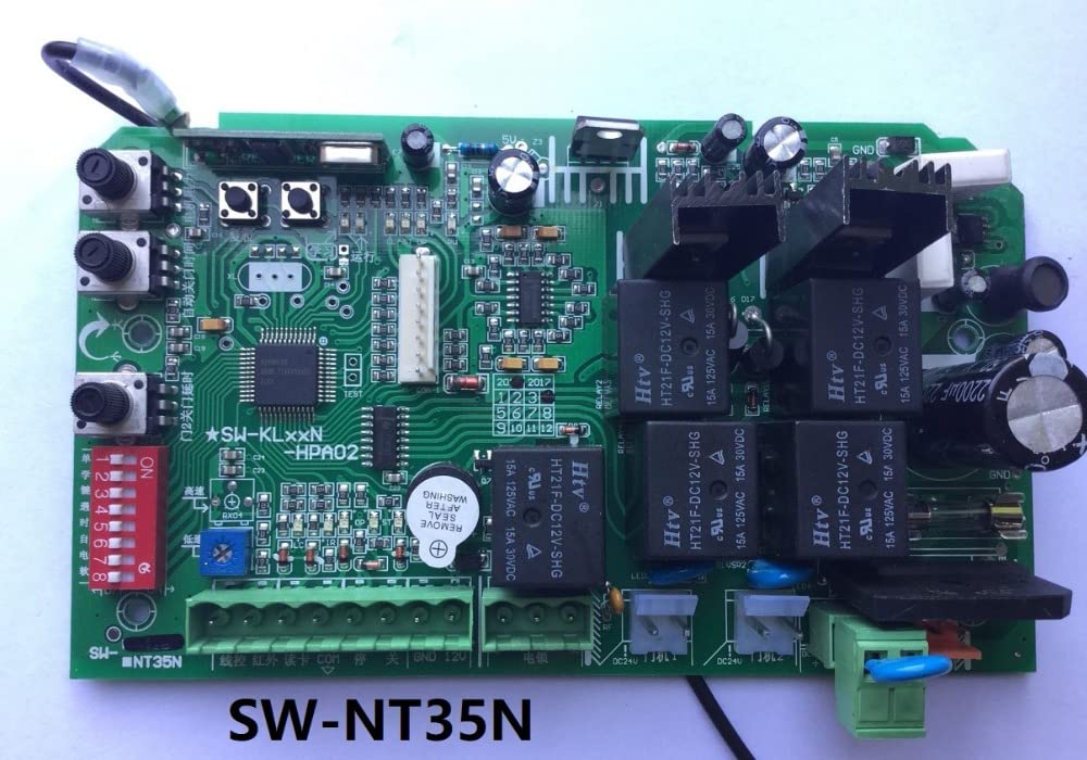
Figure 1: General view of a DAVITU Motor Driver Controller Board. This image shows the main components including relays, capacitors, and terminal blocks for connections.
Model Specifics:
- LKD-K3: A common model featuring clear terminal labels for easy wiring.
- LKD-K33: An advanced version, often with additional features or improved performance.
- SL-ST10N: Designed for specific gate motor types, offering robust control.
- PYM-200E: An earlier generation board, still widely used for its reliability.
4. Setup and Installation
Follow these steps for proper installation of your DAVITU Motor Driver Controller Board:
4.1 Mounting the Board
Mount the controller board securely within a protective enclosure, away from moisture and direct impact. Use appropriate screws and standoffs to prevent short circuits.
4.2 Wiring Connections
Refer to the specific wiring diagram for your model. The following are general connection points:
- Power Input (AC220V / AC110V): Connect the main power supply to the designated terminals (e.g., N, L). Ensure correct voltage matches the board's specification.
- Motor Output (MOTO / L1, L2, COM): Connect the slide gate motor wires to these terminals. Pay attention to motor direction.
- Limit Switches (LIMIT / COM, OP, CL): Connect the normally open (NO) or normally closed (NC) contacts of your gate's limit switches. These define the open and closed positions of the gate.
- Remote Control Receiver (KEY / ANT): Connect the remote receiver module.
- External Devices (COM, FSW, ONE, STP): Connect external safety sensors (e.g., photocells), push buttons, or other control devices.

Figure 2: DAVITU LKD-K3 Motor Driver Board showing terminal connections. Note the clearly labeled power, motor, and control input terminals.

Figure 3: DAVITU LKD-K33 Motor Driver Board with detailed wiring points. This model often includes additional features or improved layout.

Figure 4: DAVITU SL-ST10N Motor Driver Board. Observe the DIP switches for configuration and various connection points for gate control.
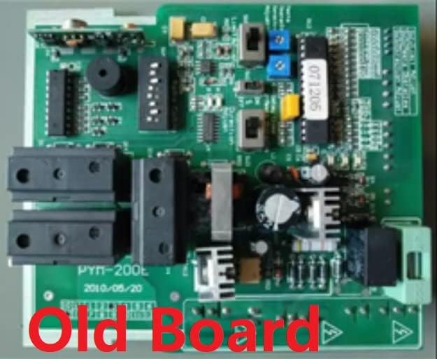
Figure 5: DAVITU PYM-200E Motor Driver Board (older version). This image highlights the layout of an earlier model, showing its components and connection areas.
4.3 Initial Power-Up and Configuration
After all wiring is complete and checked, apply power. Most boards have DIP switches or potentiometers for adjusting parameters such as motor force, soft start/stop, and auto-close time. Refer to your specific model's diagram for these settings. Many models also feature a 'LEARN' button for pairing remote controls.
5. Operating Instructions
Once installed and configured, the motor driver board operates the slide gate based on inputs from remote controls, push buttons, or safety sensors.
- Remote Control Operation: Press the designated button on your paired remote control to open, stop, or close the gate.
- Manual Operation: Use wired push buttons (if installed) for manual control.
- Safety Features: Ensure photocells or other safety sensors are functioning correctly to prevent the gate from closing on obstructions.
- Auto-Close Function: If enabled, the gate will automatically close after a set delay once it reaches the fully open position.
6. Maintenance
Regular maintenance ensures the longevity and reliable operation of your motor driver board and gate system.
- Visual Inspection: Periodically inspect the board for any signs of damage, loose connections, or corrosion.
- Cleaning: Keep the board and enclosure free from dust, dirt, and insects. Use a soft, dry brush or compressed air for cleaning.
- Wiring Check: Ensure all terminal connections are secure and free from fraying or damage.
- Limit Switch Functionality: Verify that the gate's limit switches are operating correctly and stopping the gate at the desired open and closed positions.
- Safety Sensor Test: Regularly test photocells and other safety devices to confirm they detect obstructions and prevent gate movement.
7. Troubleshooting
If you encounter issues, refer to the following common problems and solutions:
- Gate Not Responding to Remote:
- Check remote control battery.
- Ensure the remote is paired with the receiver (re-learn if necessary).
- Verify power to the controller board. - Gate Not Moving:
- Check main power supply to the board and motor.
- Inspect motor wiring for loose connections.
- Verify limit switches are not stuck in an activated position.
- Check for obstructions preventing gate movement.
- Ensure safety sensors (photocells) are not blocked or misaligned. - Gate Stops Mid-Cycle:
- Check for obstructions.
- Inspect motor for overheating.
- Verify motor force settings (if adjustable) are appropriate for the gate weight. - Gate Opens/Closes Incorrectly:
- Re-check limit switch wiring and adjustment.
- Verify motor direction wiring. - LED Indicators:
- Consult your specific model's diagram for LED status meanings, which can indicate power, signal reception, or error states.
8. Specifications
Specifications may vary by model. Please refer to the product packaging or specific model documentation for precise details.
- Brand: DAVITU
- Input Voltage: Typically AC220V or AC110V (model dependent)
- Output Voltage: Matches input voltage for motor operation
- Control Type: Microcontroller-based
- Operating Temperature: -20°C to +50°C (typical)
- Protection: Overcurrent, overvoltage (model dependent)
- Compatibility: Various slide gate motors
9. Warranty and Support
For warranty information and technical support, please contact your DAVITU product supplier or refer to the documentation provided with your specific purchase. Keep your purchase receipt as proof of purchase.