1. Introduction
This manual provides comprehensive instructions for the installation, operation, and maintenance of the DaJiKan AC2010-02 Pneumatic Air Filter Regulator Lubricator (FRL) unit. This two-piece air treatment component is designed to prepare compressed air for various pneumatic systems and tools by filtering out contaminants, regulating pressure, and providing lubrication. Proper understanding and adherence to these instructions will ensure optimal performance and longevity of the unit.
The AC2010-02 is a modular unit, allowing for easy integration and maintenance within existing pneumatic setups. Its design prioritizes ease of use and safety, featuring an integrated filter element and cup cover, along with a transparent protective cover for visibility.

Figure 1.1: DaJiKan AC2010-02 FRL unit, showing the filter, regulator, and lubricator components along with included fittings. This unit is designed to prepare compressed air for pneumatic systems.
2. Safety Information
Read all safety warnings and instructions carefully before installing or operating this product. Failure to follow these instructions may result in property damage, personal injury, or death.
- Always depressurize the air system before performing any maintenance or installation.
- Ensure the unit is installed by qualified personnel in accordance with local codes and regulations.
- Do not exceed the maximum operating pressure specified in the technical parameters.
- Use only clean, dry compressed air as the working medium.
- Avoid exposing the unit to temperatures outside the specified operating range.
- Wear appropriate personal protective equipment (PPE) when working with compressed air systems.
- Do not modify the unit. Unauthorized modifications can lead to malfunction and void the warranty.
3. Component Identification
The DaJiKan AC2010-02 FRL unit consists of several key components. Familiarize yourself with these parts before installation and operation.
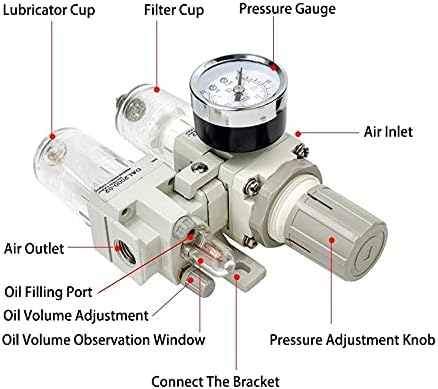
Figure 3.1: Detailed view of the AC2010-02 FRL unit with key components labeled, including the lubricator cup, filter cup, pressure gauge, air inlet, air outlet, oil filling port, oil volume adjustment, oil volume observation window, and pressure adjustment knob.
- Air Inlet: Connection point for incoming compressed air.
- Air Outlet: Connection point for treated compressed air to the pneumatic system.
- Pressure Gauge: Displays the regulated output pressure.
- Pressure Adjustment Knob: Used to set the desired output pressure.
- Filter Cup: Collects moisture and particulate matter from the air.
- Lubricator Cup: Holds lubricating oil for pneumatic tools.
- Oil Filling Port: Point for adding lubricating oil to the lubricator cup.
- Oil Volume Adjustment: Controls the amount of oil dispensed into the air stream.
- Oil Volume Observation Window: Allows visual inspection of oil level and drip rate.
- Manual Drain Valve: Located at the bottom of the filter cup for manual condensate removal.
4. Setup and Installation
Follow these steps for proper installation of the FRL unit.
- Mounting: Securely mount the FRL unit to a stable surface using the provided bracket. Ensure it is installed vertically with the drain valves at the bottom for effective moisture removal.
- Air Connections: Connect the main air supply line to the Air Inlet and the pneumatic system line to the Air Outlet. Ensure all connections are tight and leak-free. Use appropriate thread sealant if necessary.
- Lubricator Oil Fill: If lubrication is required for your pneumatic tools, unscrew the Oil Filling Port cap and fill the Lubricator Cup with the recommended pneumatic tool oil (ISO VG32). Do not overfill. Replace the cap securely.
- Initial Pressure Setting: Before applying air pressure, turn the Pressure Adjustment Knob counter-clockwise to its lowest setting.
5. Operating Instructions
Once installed, operate the FRL unit as follows:
- Apply Air Pressure: Slowly open the main air supply valve to introduce compressed air into the FRL unit.
- Adjust Output Pressure: Turn the Pressure Adjustment Knob clockwise to increase the output pressure. Observe the Pressure Gauge and set it to the desired operating pressure for your pneumatic tools or system. Pull up the knob to unlock, adjust, then push down to lock the setting.
- Adjust Lubrication (if applicable): If using the lubricator, adjust the Oil Volume Adjustment screw to achieve the desired oil drip rate. Observe the oil drops through the Oil Volume Observation Window. Start with a low setting and increase gradually if needed.
- Monitor Performance: Regularly check the pressure gauge and the clarity of the filter cup for accumulated moisture.
6. Maintenance
Regular maintenance ensures the efficiency and longevity of your FRL unit.
- Drain Condensate: Manually drain accumulated moisture from the Filter Cup regularly by opening the manual drain valve at the bottom. Frequency depends on air quality and usage.
- Check Oil Level: Periodically check the oil level in the Lubricator Cup via the Oil Volume Observation Window. Refill with ISO VG32 pneumatic tool oil as needed.
- Filter Element Replacement: The filter element should be inspected periodically and replaced when it appears clogged or when pressure drop across the filter becomes significant. The filter element and cup cover are integrated for easy replacement.
- Cleaning: Clean the exterior of the unit with a damp cloth. Do not use solvents that may damage plastic components.
7. Troubleshooting
Refer to the table below for common issues and their solutions.
| Problem | Possible Cause | Solution |
|---|---|---|
| No air flow or low pressure at outlet. |
|
|
| Excessive moisture in air line. |
|
|
| No oil drip from lubricator. |
|
|
8. Specifications
Technical parameters for the DaJiKan AC2010-02 FRL unit:

Figure 8.1: Technical specifications table for the AC2010-02 FRL unit, detailing thread type, pore size, working fluid, maximum pressure, operating pressure, temperature range, filtration accuracy, recommended oil, body material, inner cup material, shield material, pressure range, water filter cup capacity, and oil supply cup capacity.
| Parameter | Value |
|---|---|
| Model | AC2010-02 |
| Thread Type | Rc |
| Pore Size | 1/4" |
| Working Fluid | Air |
| MAX. Press | 9.9 kgf/cm² |
| MAX. Operating Pressure | 9 kgf/cm² |
| Environment and fluid temperature | -5~60℃ (Not frozen) |
| Filtration accuracy | Copper Filter: 15um, Fiber Filter: 40um |
| Recommended oil | ISOVG32 |
| Body Material | Aluminum |
| Inner Cup Material | Polycarbonate (PC) |
| Shield Material | Metal |
| Pressure range | 0.05~0.85Mpa |
| Water Filter Cup Capacity | 10 CC |
| Oil Supply Cup Capacity | 25 CC |
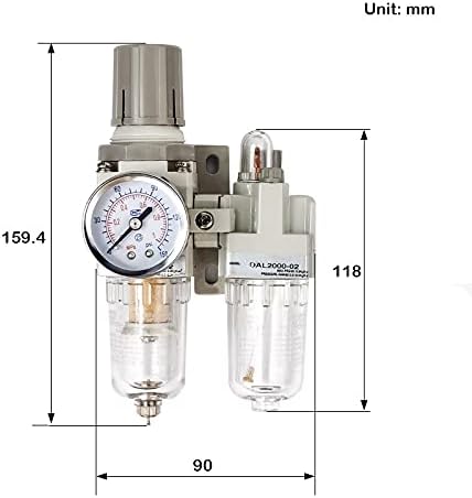
Figure 8.2: Dimensional drawing of the AC2010-02 FRL unit, showing key measurements in millimeters for installation planning.
9. Warranty and Support
For warranty information or technical support, please contact your retailer or the manufacturer directly. Keep your purchase receipt as proof of purchase.
Manufacturer: DaJiKan