1. Introduction
This HDMI 200M Extender over IP system is designed to transmit high-definition video and audio signals, along with USB keyboard and mouse control, over a single CAT5e/6/6a/7 Ethernet cable. It supports transmission distances up to 200 meters (656 feet) and is based on the TCP/IP standard. The system offers versatile connection modes including point-to-point, one-to-many, and cascade connections, making it suitable for various applications.
Key features include:
- Supports IR remote control extension.
- Extends USB mouse and keyboard signals.
- Transmits HDMI 1080P signals up to 200m (CAT6), 150m (CAT5e), or 120m (CAT5).
- Pure hardware design, plug-and-play operation, no additional software required.
- Supports point-to-point, one-to-many (up to 20 receivers with a network switch), and cascade connection modes.
- Utilizes advanced H.264 HDMI audio/video decoding for high-quality streaming with low latency (approximately 500ms).
Note: CAT6/6a or CAT7 cable is recommended for optimal performance. CAT5e may not provide sufficient bandwidth for all applications.
2. Package Contents
The standard package for one set (TX+RX) includes the following items:
- 1 x HDMI KVM IP Extender Transmitter (TX) unit
- 1 x HDMI KVM IP Extender Receiver (RX) unit
- 2 x AC Power Supply Adapters (DC: 5V/1A)
- 1 x User Guide (this manual)
- 2 x IR Cables (1 for TX, 1 for RX)
3. Product Overview
The HDMI KVM IP Extender system consists of two main units: a Transmitter (TX) and a Receiver (RX). Both units are compact and designed for easy integration into various setups.

Figure 3.1: HDMI KVM IP Extender Transmitter (TX) Unit. This unit connects to the HDMI source and sends the signal over the network cable.

Figure 3.2: HDMI KVM IP Extender Receiver (RX) Unit. This unit connects to the HDMI display and receives the signal from the network cable.
3.1 Interface Description
Both the Transmitter and Receiver units feature clearly labeled ports for easy connection. Refer to the diagram below for a detailed view of the interfaces.

Figure 3.3: Interface Display for both Transmitter (top) and Receiver (bottom) units.
| Port | Description | Unit |
|---|---|---|
| DC/5V | Power Supply Interface (connect included 5V/1A power adapter) | TX & RX |
| HDMI IN | HDMI Input (connect to HDMI source like PC, DVD, STB) | TX |
| HDMI OUT | HDMI Output (connect to local HDMI display on TX, or remote display on RX) | TX & RX |
| IR RX | Infrared Receiver Port (connect IR receiver cable) | TX |
| IR TX | Infrared Transmitter Port (connect IR transmitter cable) | RX |
| USB1/USB2 | USB Interface (connect USB keyboard/mouse or other USB devices) | TX & RX |
| Ethernet | Cable Interface (RJ45 port for CAT5e/6/6a/7 cable connection) | TX & RX |
4. Setup and Installation
Follow these steps to set up your HDMI KVM IP Extender system. Ensure all devices are powered off before making connections.
4.1 Point-to-Point Connection
This is the simplest setup, connecting one Transmitter to one Receiver directly via an Ethernet cable.
- Connect your HDMI source (e.g., PC, DVD player) to the HDMI IN port of the Transmitter (TX) unit using an HDMI cable.
- (Optional) Connect a local HDMI display to the HDMI OUT port of the TX unit if you wish to monitor the source locally.
- Connect your USB keyboard and mouse to the USB1 and USB2 ports of the TX unit.
- Connect the IR receiver cable to the IR RX port on the TX unit and position the IR eye near your source device's IR sensor.
- Connect the Ethernet port of the TX unit to the Ethernet port of the Receiver (RX) unit using a single CAT5e/6/6a/7 cable.
- Connect your remote HDMI display (e.g., TV, projector) to the HDMI OUT port of the RX unit using an HDMI cable.
- Connect your USB keyboard and mouse to the USB1 and USB2 ports of the RX unit.
- Connect the IR transmitter cable to the IR TX port on the RX unit and position the IR emitter near the IR sensor of the device you wish to control remotely.
- Connect the provided 5V/1A power adapters to the DC/5V ports of both the TX and RX units, then plug them into power outlets.
- Power on all connected devices.

Figure 4.1: Basic Point-to-Point Connection Diagram.

Figure 4.2: Detailed Point-to-Point Application Diagram showing various source and display types.
4.2 Point-to-Multipoint Application
This setup allows one Transmitter to send signals to multiple Receivers using a network switch (interchanger). This is ideal for distributing a single HDMI source to many displays.
- Connect your HDMI source to the HDMI IN port of the Transmitter (TX) unit.
- Connect the Ethernet port of the TX unit to an available port on a network switch (interchanger).
- Connect the Ethernet port of each Receiver (RX) unit to an available port on the same network switch.
- Connect each RX unit's HDMI OUT port to its respective HDMI display.
- Connect USB keyboard/mouse and IR cables to the TX and RX units as needed for KVM and IR extension.
- Power on all units and the network switch.
Figure 4.3: Point-to-Multipoint Application Diagram. Note the use of a network switch.
Important: For one-to-many and cascade modes, a network switch (interchanger) is required. The system supports up to 20 Receivers (RX) with an 802.3 Ethernet standard compliant switch.
4.3 Cascade Connection Mode
The cascade connection allows for extending the signal over longer distances or to more complex network topologies by linking multiple network switches.
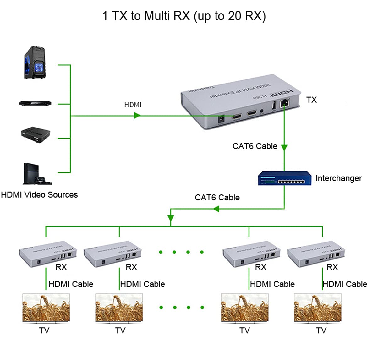
Figure 4.4: Cascade Connection Diagram, illustrating how multiple receivers can be connected via a network switch.
In a cascade setup, the Transmitter connects to a network switch, and additional switches can be connected to the first switch to expand the network. Receivers are then connected to any of these switches. This allows for flexible and scalable distribution of the HDMI signal across a larger area or to a greater number of displays.
5. Operating Instructions
Once the system is set up according to the desired connection mode, operation is straightforward due to its plug-and-play design.
- Power On: Ensure both the TX and RX units are powered by their respective 5V/1A adapters. Power indicator lights should illuminate.
- Signal Transmission: The extender will automatically detect and transmit the HDMI signal from the source to the connected display(s).
- KVM Functionality: If USB keyboard and mouse are connected, they will function seamlessly across the extended distance, allowing control of the source device from the remote location.
- IR Control: With the IR cables properly connected and positioned, you can use your source device's remote control from the remote display location to control the source device.
- Resolution Support: The system supports resolutions up to 1080p (480p, 720p, 1080p). The display will automatically adjust to the source's resolution.
- Audio Support: Audio is transmitted along with the video, supporting sample rates of 32kHz, 44.1kHz, and 48kHz.
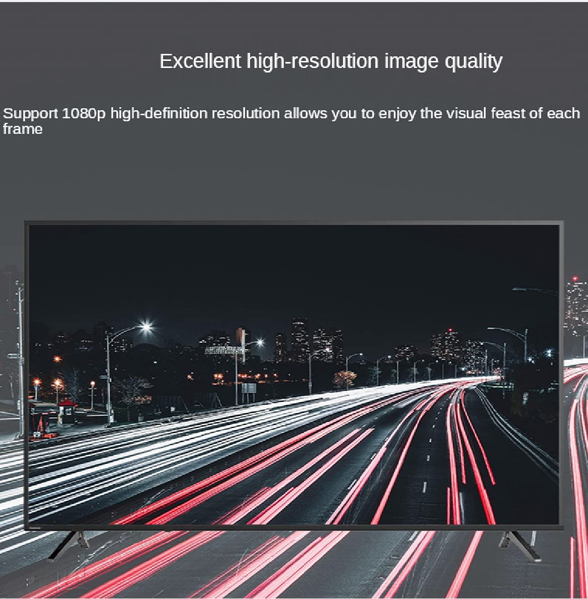
Figure 5.1: The extender supports excellent high-resolution image quality, up to 1080p.
6. Specifications
| Feature | Detail |
|---|---|
| HDMI Version | HDMI 1.3 |
| Resolutions Supported | 480p, 720p, 1080p |
| Audio Sample Rate | 32kHz, 44.1kHz, 48kHz |
| IR Remote Control Frequency | 38 KHz (NEC compatible) |
| Transmission Distance (CAT6) | Up to 200 meters (656 feet) |
| Transmission Distance (CAT5e) | Up to 150 meters |
| Transmission Distance (CAT5) | Up to 120 meters |
| Power Adapter | DC 5V/1A |
| Power Consumption (TX) | 3W |
| Power Consumption (RX) | 3W |
| Dimensions (L-W-H) | Approx. 163 x 87 x 24 mm |
| Operating Mode | Manual-Automatic |
| Item Model Number | BW-HKE200 |
7. Troubleshooting
If you encounter issues with your HDMI KVM IP Extender, please refer to the following common troubleshooting steps:
- No Video/Audio Output:
- Ensure both TX and RX units are powered on and their power indicator lights are illuminated.
- Verify all HDMI and Ethernet cables are securely connected and not damaged.
- Check if the HDMI source device is outputting a signal and the display is set to the correct HDMI input.
- Try a different HDMI cable or Ethernet cable.
- Ensure the Ethernet cable used is CAT6 or higher for optimal performance, especially over longer distances.
- If using a network switch, ensure it is powered on and functioning correctly. Try connecting TX and RX directly (point-to-point) to rule out network issues.
- KVM (Keyboard/Mouse) Not Responding:
- Ensure USB cables are firmly connected to both the TX and RX units.
- Try connecting the keyboard/mouse directly to the source device to confirm they are working.
- Test with different USB ports on the extender units.
- Some specialized gaming keyboards/mice with high power requirements or complex drivers may not be fully supported. Try a standard keyboard/mouse.
- IR Control Not Working:
- Ensure the IR receiver cable is connected to the TX unit and the IR emitter cable is connected to the RX unit.
- Verify the IR receiver eye is positioned directly in front of the source device's IR sensor.
- Ensure the IR emitter is positioned directly in front of the device you wish to control remotely.
- Check if the remote control itself is working by testing it directly with the source device.
- Intermittent Signal/Flickering:
- This can often be caused by poor quality or overly long Ethernet cables. Replace with a high-quality CAT6/6a/7 cable.
- Ensure there are no strong electromagnetic interferences near the cables or units.
- Check power connections for stability.
If the issue persists after trying these steps, please contact customer support for further assistance.
8. Maintenance
The HDMI KVM IP Extender is designed for reliable operation with minimal maintenance. Follow these guidelines to ensure longevity:
- Cleaning: Use a soft, dry cloth to clean the units. Do not use liquid cleaners or aerosol sprays.
- Environment: Operate the device in a dry, well-ventilated area, away from direct sunlight, heat sources, and excessive dust.
- Power: Always use the provided 5V/1A power adapters. Using incorrect power adapters can damage the device.
- Handling: Avoid dropping or subjecting the units to strong impacts.
- Cables: Ensure cables are not bent sharply or pinched, which can damage internal wires.
9. Warranty and Support
This product is manufactured by Swallow house. For specific warranty information, please refer to the warranty card included with your purchase or contact the seller directly. Keep your purchase receipt as proof of purchase for any warranty claims.
For technical support or further inquiries, please contact Swallow house customer service through the platform where you purchased the product or refer to the contact information provided in the product packaging.


