1. Introduction
This instruction manual provides detailed guidance for the installation, operation, and maintenance of your xhtechnology 4 Gang Rocker Switch Panel. This multi-function panel is designed for various 12V/24V DC applications, including automotive vehicles, boats, RVs, and SUVs. It features four LED illuminated ON-OFF rocker switches, a 3.1A dual USB charger, and a 12V/24V DC power socket, all within a waterproof housing.
Please read this manual thoroughly before installation and use to ensure proper function and safety.
2. Product Features
- Integrated Voltmeter & Dual USB Ports: Includes dual USB ports (5V/1A and 5V/2.1A) for charging devices, a 12V/24V DC power socket, and a cigarette lighter slot.
- Enhanced Safety and Durability: Certified with CE, FCC, and ROHS. Constructed with H65 copper and silver plating, a heavy-duty ABS fire-resistant UL94-V1 panel, and a built-in DC32V overcurrent protector. Contacts are made of silver-tin alloy for stable circuit operation.
- Multifunctional Application: Suitable for controlling various electrical appliances in passenger cars, RVs, yachts, and ships, such as air conditioners, lamps, and exhaust fans.
- IP65 Waterproof Rating: Features a splash-proof waterproof panel to prevent water ingress, ensuring internal components remain dry and preventing short circuits.
3. Package Contents
Verify that all items listed below are included in your package:
- 1 x xhtechnology 4 Gang Rocker Switch Panel
- 4 x Mounting Screws (M4*20mm self-tapping)
- 2 x DIY Sticker Sheets (transparent with various icons)
- 1 x Instruction Manual
- 1 x EVA Shock-absorbing Rubber Pad

Image 3.1: Contents of the xhtechnology 4 Gang Rocker Switch Panel package, including the panel, screws, stickers, and manual.
4. Specifications
| Model Number | QYPCMY0009 |
| Product Dimensions (L x W x H) | 5.1 x 4.7 x 3.1 inches |
| Operating Voltage | 12V / 24V DC |
| Current Rating | 20 Amps |
| Operation Mode | ON-OFF |
| Contact Type | Normally Open |
| Connector Type | Plug In |
| Terminal Type | 250 Plug Spring Quick Connect Terminal |
| USB Output | 5V/1A, 5V/2.1A (Total 3.1A) |
| Waterproof Rating | IP65 (Splash-proof front panel) |

Image 4.1: Detailed product dimensions and a basic wiring diagram for the switch panel.
5. Safety Information
Always observe the following safety precautions during installation and operation:
- Disconnect the vehicle's or vessel's power source (battery) before beginning any electrical work to prevent electrical shock or short circuits.
- Ensure all wiring connections are secure and properly insulated to prevent loose connections and potential hazards.
- Do not exceed the maximum current rating of 20 Amps for the panel. Use appropriate fuses for each circuit.
- Verify that the operating voltage (12V/24V DC) matches your application's electrical system.
- Avoid exposing the rear of the panel to direct water spray or submersion, as only the front panel is IP65 rated.
- If you are unsure about any part of the installation process, consult a qualified electrician or automotive technician.
6. Setup and Installation
6.1 Mounting the Panel
- Choose a suitable flat surface for mounting the switch panel. Ensure there is enough space behind the panel for wiring connections.
- Using the provided dimensions (refer to Image 4.1), mark the cutout area and screw hole positions on your chosen mounting surface.
- Carefully cut out the opening for the panel.
- Insert the switch panel into the cutout.
- Secure the panel using the four M4*20mm self-tapping screws provided.
- Apply the EVA shock-absorbing rubber pad behind the panel if desired for added stability and vibration dampening.
6.2 Wiring Connections
Refer to the wiring diagram (Image 4.1) for detailed connection points. The panel is pre-wired for convenience.
- Power Input: Connect the main positive (+) wire from your power source to the red wire of the panel's main input. Connect the main negative (-) wire to the black wire. Ensure an inline fuse is installed on the positive line for protection.
- Accessory Connections: Each rocker switch has a corresponding output wire (typically blue or yellow, depending on the specific circuit). Connect the positive (+) wire of your accessory (e.g., lights, fan) to the output wire of the desired switch. The negative (-) wire of the accessory should be connected to a common ground point.
- USB Charger/Power Socket: These components are typically pre-wired to the main power input. Ensure they receive appropriate voltage.

Image 6.1: Example of the switch panel integrated into a boat's dashboard, demonstrating a typical installation scenario.

Image 6.2: The 4 Gang Rocker Switch Panel shown installed in a vehicle's dashboard, highlighting its compact fit.
7. Operating Instructions
7.1 Rocker Switches
Each rocker switch controls a separate circuit. To activate an connected accessory, press the top part of the rocker switch. The integrated LED light will illuminate, indicating the circuit is active. To deactivate, press the bottom part of the switch. The LED will turn off.
7.2 Dual USB Charger and DC Power Socket
The dual USB ports provide 5V/1A and 5V/2.1A output for charging compatible electronic devices. Simply plug your USB charging cable into the appropriate port. The DC power socket (cigarette lighter style) can be used for devices requiring 12V/24V DC power, such as portable air compressors or GPS units.
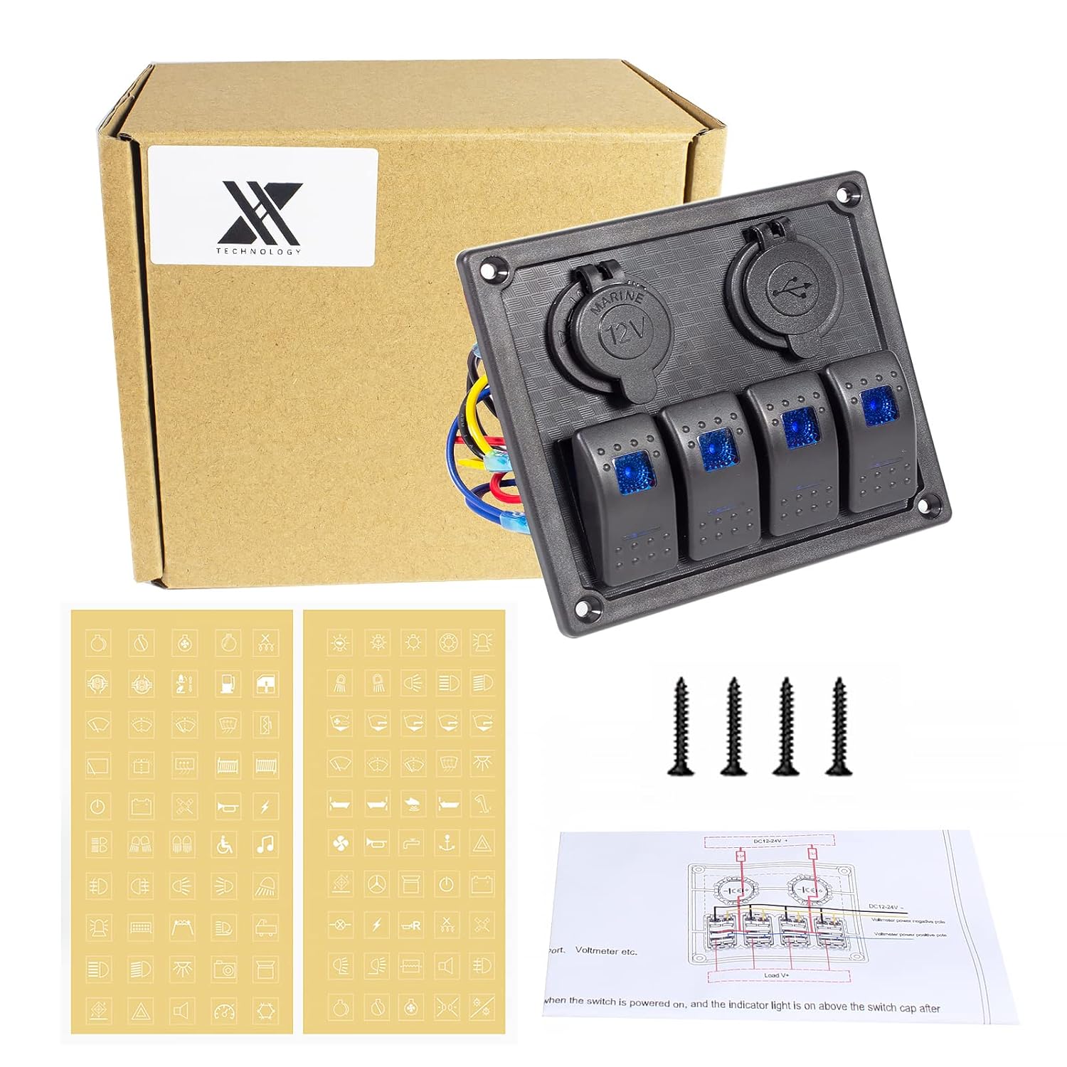
Image 7.1: A detailed view of the dual USB charging ports, showing the 5V/1A and 5V/2.1A outputs.

Image 7.2: Specifications for the 12V 2.1A USB charger, indicating input voltage and output current/voltage.

Image 7.3: The USB port power outlet, designed for easy installation and quick device connection.
7.3 Applying DIY Stickers
The package includes two sheets of transparent DIY stickers with various icons. These stickers can be applied to the rocker switches to label their functions (e.g., lights, horn, fan). Peel off the desired sticker and carefully apply it to the switch surface.

Image 7.4: The included DIY sticker sheets and a demonstration of how to apply a sticker to a rocker switch for function labeling.

Image 7.5: The DIY sticker sheets provided for customizing the switch panel with various functional icons.
8. Maintenance
Regular maintenance ensures the longevity and optimal performance of your switch panel.
- Cleaning: Wipe the front panel with a soft, damp cloth. Avoid using abrasive cleaners or solvents that could damage the surface or waterproof seals.
- Waterproofing: While the front panel is IP65 splash-proof, ensure the protective caps for the USB ports and DC socket are securely closed when not in use, especially in marine environments or during wet conditions.
- Connection Checks: Periodically inspect all wiring connections for tightness and signs of corrosion. Address any loose or corroded connections promptly.
- Fuse Inspection: If a circuit fails, check the corresponding fuse in your vehicle's or vessel's fuse box, or any inline fuses installed. Replace blown fuses with ones of the correct amperage.

Image 8.1: The switch panel showcasing its IP65 waterproof front panel, designed to withstand splashes and moisture.
9. Troubleshooting
If you encounter issues with your switch panel, refer to the following common problems and solutions:
- No Power to Panel/Switches:
- Check the main power connection to the panel.
- Verify the vehicle's/vessel's battery is charged and connected.
- Inspect the main fuse for the panel's power input.
- Switch LED Not Illuminating / Accessory Not Working:
- Ensure the accessory is properly wired to the switch output.
- Check the fuse for the specific accessory circuit.
- Verify the accessory itself is functional.
- USB Ports Not Charging:
- Confirm the panel is receiving power.
- Check the USB cable and the device being charged.
- Ensure the device's power requirements do not exceed the USB port's output (5V/3.1A total).
- Water Ingress:
- Ensure all protective caps for the USB and DC ports are sealed when not in use.
- Verify the panel is correctly installed in its cutout to maintain the front panel's waterproof seal.
10. Warranty and Support
xhtechnology products are manufactured to high-quality standards. For any warranty claims or technical support, please contact your retailer or visit the official xhtechnology brand store for assistance.
For more information and support, please visit the xhtechnology Store.