1. Introduction
The Vbestlife AT5-2200X Variable Frequency Drive (VFD) is an advanced device designed for precise control of three-phase AC motors. It converts single-phase AC power into three-phase AC power with variable frequency and voltage, allowing for adjustable motor speed and torque. This VFD is suitable for applications requiring fine-tuned motor control, energy efficiency, and enhanced operational stability.
This manual provides essential information for the safe and effective installation, operation, and maintenance of your AT5-2200X VFD. Please read it thoroughly before use.
2. Safety Precautions
WARNING: Improper installation or operation can lead to electric shock, fire, or equipment damage. Always follow these safety guidelines.
- Ensure the power supply is disconnected before any wiring or maintenance.
- Only qualified personnel should install, operate, and maintain this device.
- Connect the VFD to a proper ground.
- Do not connect the VFD output (U, V, W) to the AC power supply.
- Do not open the VFD casing while power is applied or shortly after power-off, as residual voltage may be present.
- Avoid installing the VFD in environments with high temperature, humidity, dust, or corrosive gases.
- Ensure proper ventilation around the unit.

Image: Top view of the Vbestlife AT5-2200X Variable Frequency Drive, highlighting the control panel and a visible safety warning label on the side.
3. Product Features
- Adjusts motor speed with high torque and wide speed regulation capabilities.
- Equipped with a digital display for clear readings and convenient parameter configuration.
- Comprehensive protection features: overcurrent, overvoltage, undervoltage, module failure, overheating, short circuit, input/output phase loss, abnormal motor parameter adjustment, and electronic thermal relay.
- Provides low electromagnetic interference for stable operation.
- Single-phase 110V AC input and three-phase 220V AC output, suitable for 2.2kW three-phase motors.
- Controls motor start, stop, speed adjustment, and forward/reverse rotation to meet diverse equipment requirements.
4. Product Overview and Components
The Vbestlife AT5-2200X VFD consists of a main unit with a control panel, cooling vents, and terminal blocks for electrical connections. The digital display and buttons on the control panel allow for monitoring and adjusting operational parameters.
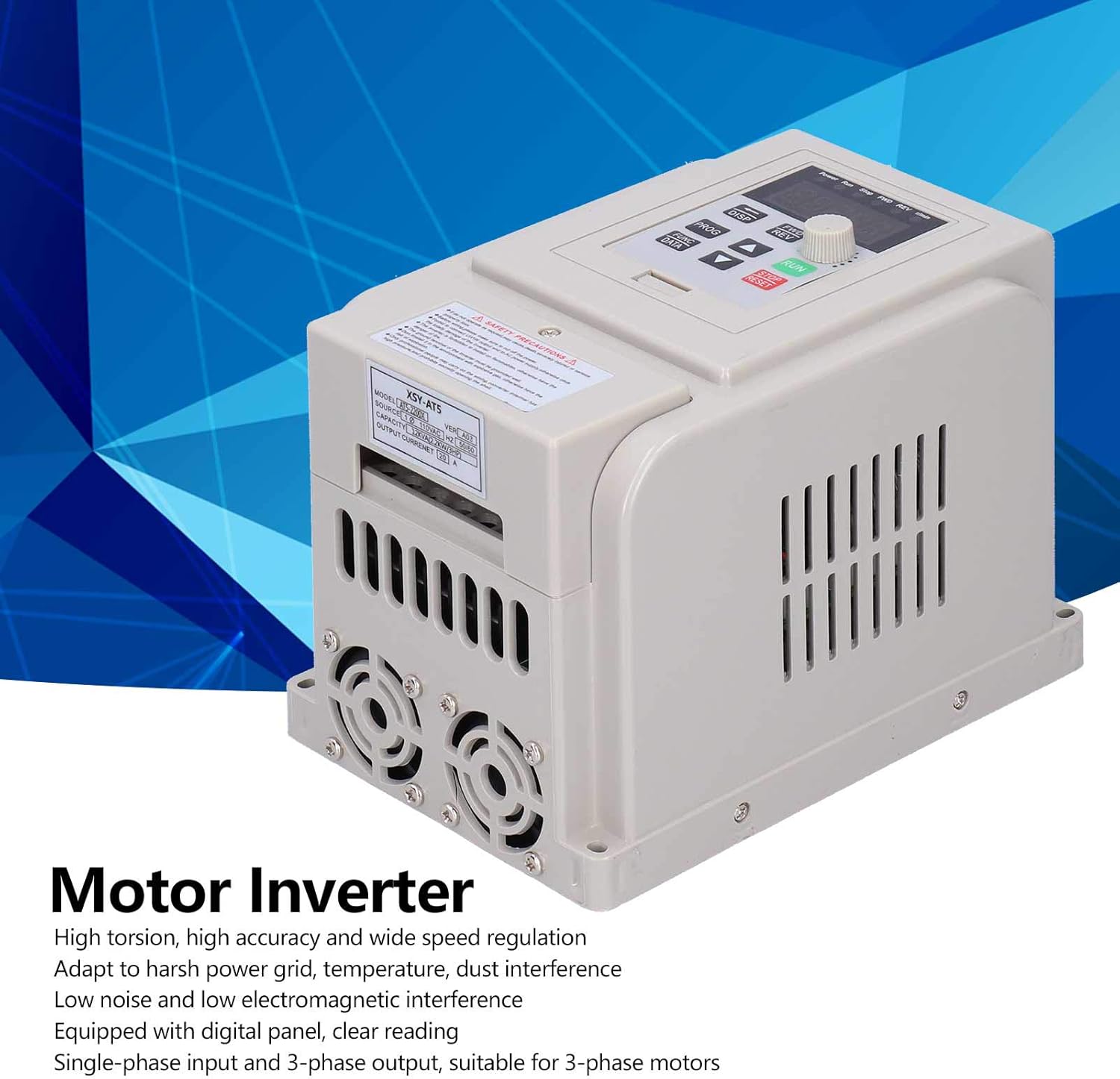
Image: Front-side view of the Vbestlife AT5-2200X Variable Frequency Drive, labeled as a 'Motor Inverter'.

Image: Side view of the Vbestlife AT5-2200X VFD, showing the cooling fans at the bottom for heat dissipation.
5. Specifications
| Parameter | Value |
|---|---|
| Item Type | Variable Frequency Inverter |
| Model | AT5-2200X |
| Rated Power | 2200W (2.2kW) |
| Power Phase Number | Single-phase input |
| Input Voltage | Single-phase 110V AC (50/60Hz) |
| Output Voltage | Three-phase 220V AC |
| Display | Digital |
| Protection Mode | Overcurrent, Overvoltage, Undervoltage, Module Failure, Overheating, Short Circuit, Input/Output Phase Loss, Abnormal Motor Parameter Adjustment, Electronic Thermal Relay |
| Recommended Uses | Speed control of three-phase motors and powering equipment with 220V input requiring precise motor speed control. |
| Material | Plastic |
| Country of Origin | China |
Note: This inverter is specifically designed for use with three-phase 220V motors. Please verify compatibility with your motor before installation.
6. Setup and Installation
Proper installation is crucial for the safe and efficient operation of the VFD. Refer to the wiring diagram provided with your unit for specific connection points. The general steps are as follows:
- Mounting: Securely mount the VFD in a well-ventilated area, away from direct sunlight, excessive heat, moisture, and vibrations. Ensure adequate clearance for airflow around the cooling vents.
- Power Input (L, N, G): Connect the single-phase 110V AC power supply to the designated input terminals (L for Line, N for Neutral). Connect the ground wire to the ground terminal (G).
- Motor Output (U, V, W): Connect the three-phase motor wires to the VFD's output terminals (U, V, W). Ensure correct phase sequence for desired motor rotation.
- Control Wiring (Optional): If using external control signals (e.g., potentiometer for speed, external start/stop buttons), connect them to the appropriate control terminals as per the detailed wiring diagram in the full user manual.
- Initial Check: Before applying power, double-check all wiring connections for tightness and correctness.

Image: Side view of the Vbestlife AT5-2200X VFD, showing its compact design and cooling fins.
7. Operating Instructions
The VFD's control panel allows for basic operation and parameter adjustments. Familiarize yourself with the buttons and digital display.
7.1 Basic Operation
- Power On: After verifying all connections, apply power to the VFD. The digital display will light up.
- Start: Press the RUN button to start the motor. The motor will accelerate to the set frequency.
- Stop: Press the STOP/RESET button to stop the motor.
- Speed Adjustment: Use the rotary knob or the UP/DOWN arrow buttons to adjust the output frequency, thereby changing the motor speed.
- Forward/Reverse: Use the FWD/REV button or corresponding control terminals to change the motor's direction of rotation.
7.2 Parameter Setting
The VFD has various parameters that can be configured to optimize performance for specific applications. These parameters control aspects such as acceleration/deceleration times, motor characteristics, and protection thresholds. Refer to the detailed parameter list in the complete user manual for specific codes and their functions.
To enter parameter setting mode, typically press the PROG or FUNC/DATA button. Use the UP/DOWN arrows to navigate through parameters and the rotary knob or ENTER button to modify values. Always save changes before exiting the parameter setting mode.
Video: An overview of a Variable Frequency Drive, demonstrating its general appearance and basic functions. This video is provided by a seller.
Video: Demonstration of setting parameters on a Variable Frequency Drive, including voltage and current settings. This video is provided by a seller and shows a similar VFD model.
8. Maintenance
Regular maintenance ensures the longevity and reliable operation of your VFD.
- Cleaning: Periodically clean the VFD's exterior and cooling vents to prevent dust accumulation, which can hinder heat dissipation. Use a soft, dry cloth. Do not use liquid cleaners.
- Inspection: Regularly inspect all wiring connections for tightness and signs of wear or damage. Check for any unusual noises or odors during operation.
- Environment: Ensure the operating environment remains within the specified temperature and humidity ranges.
- Capacitor Life: Electrolytic capacitors have a finite lifespan. If the VFD is used continuously for many years, consider professional inspection or replacement of capacitors.
9. Troubleshooting
This section provides solutions for common issues. For complex problems, contact technical support.
| Problem | Possible Cause | Solution |
|---|---|---|
| VFD does not power on | No input power, faulty wiring, internal fuse blown | Check power supply, verify wiring, inspect fuses (by qualified personnel) |
| Motor does not run | Incorrect wiring, parameter settings, motor fault, VFD in fault state | Check motor and VFD wiring, verify parameter settings (e.g., FWD/REV), check motor for issues, clear VFD fault (STOP/RESET) |
| Overcurrent fault (OC) | Motor overload, short circuit in motor wiring, rapid acceleration/deceleration | Reduce motor load, check motor wiring, increase acceleration/deceleration times in parameters |
| Overvoltage fault (OV) | High input voltage, rapid deceleration, regenerative braking | Check input voltage, increase deceleration time, consider braking resistor if necessary |
| Undervoltage fault (UV) | Low input voltage, power supply instability | Check input voltage, ensure stable power supply |
10. Warranty and Support
For warranty information, please refer to the terms and conditions provided at the time of purchase or contact your retailer. Vbestlife is committed to providing quality products and support.
If you encounter issues not covered in this manual or require technical assistance, please contact Vbestlife customer support or your authorized dealer. When contacting support, please have your product model (AT5-2200X) and a detailed description of the issue ready.