1. Introduction
This manual provides comprehensive instructions for the installation, operation, and maintenance of your LoraTap Wireless Switch Kit. This kit allows you to control lighting and ventilation systems wirelessly, offering convenience and flexibility. Please read this manual thoroughly before installation and use to ensure proper function and safety.
2. Product Overview
The LoraTap Wireless Switch Kit consists of a receiver module and a wireless transmitter (remote control).

Figure 1: LoraTap Wireless Switch Kit showing the compact receiver module and the portable remote control.
2.1. Receiver Module
- Function: Connects to your electrical load (e.g., light, fan) and receives wireless signals from the transmitter.
- Dimensions: 4.6 x 4.6 x 1.8 cm
- Input: 100-250 VAC, 50/60 Hz
- Output: 100-250 V AC, 50/60 Hz
- Maximum Load: 10A
- Maximum Power:
- LED, fluorescent lamps: up to 300W (10A)
- Incandescent, tungsten, halogen lamps: up to 2500W (10A)
- Other electrical appliances: up to 2500W (10A)
2.2. Wireless Transmitter (Remote Control)
- Function: Sends wireless signals to the receiver to control the connected appliance. Features ON, OFF, 10-minute timer, and 30-minute timer buttons.
- Dimensions: 6.8 x 1.6 cm (diameter x thickness)
- Wireless Range: Up to 30 meters indoors (even through walls), up to 200 meters outdoors (without obstacles).
- Radio Frequency: 868 MHz, with self-learning program for high security.
- Lifespan: Over 220,000 clicks.
- Battery Type: CR2032 (included).
- Portability: The transmitter is removable from its magnetic base, allowing it to be used as a portable remote or fixed to a wall using the included double-sided adhesive.

Figure 2: The portable and versatile LoraTap remote control.
3. Safety Information
- Ensure power is disconnected before installing or performing any maintenance on the receiver module.
- Do not exceed the maximum load and power ratings specified for the receiver.
- This product is designed for indoor use primarily, though the transmitter has an extended outdoor range.
- Keep the device away from water and extreme temperatures.
- This product is not compatible with Wi-Fi, Alexa Echo, or Google Home.
4. Installation
The LoraTap Wireless Switch Kit is designed for easy installation without the need for extensive wiring or wall damage.
4.1. Receiver Module Installation
- Disconnect Power: Before starting, turn off the main power supply to the circuit where you intend to install the receiver.
- Wiring: Connect the receiver module according to the wiring diagram.

Figure 3: Receiver Wiring Diagram. Connect Live (L) and Neutral (N) from your power source to the receiver's input. Connect the Live (L) and Neutral (N) of your lamp or appliance to the receiver's output.
- Connect the Live (L) wire from your power source to the receiver's "Input L" terminal.
- Connect the Neutral (N) wire from your power source to the receiver's "Input N" terminal.
- Connect the Live (L) wire of your lamp/appliance to the receiver's "Output L" terminal.
- Connect the Neutral (N) wire of your lamp/appliance to the receiver's "Output N" terminal.
- Placement: The compact size of the receiver allows it to be placed in a junction box, behind a traditional wall switch, or in the ceiling near the light fixture.
- Restore Power: Once wiring is complete and secure, restore power to the circuit.
4.2. Transmitter (Remote Control) Installation
- Magnetic Base: The transmitter comes with a magnetic base. You can attach this base to any flat surface using the included double-sided adhesive or screws.
- Placement: Choose a convenient location for your wall switch, such as near a door, bedside, or on a piece of furniture.
- Attachment: The transmitter magnetically attaches to its base, allowing it to be easily removed for portable use.

Figure 4: Example installation showing the receiver behind a wall switch and the remote controlling devices wirelessly.
5. Pairing Instructions
The transmitter and receiver are usually pre-paired. If re-pairing is needed or if you wish to pair additional transmitters/receivers, follow these steps:
- Enter Pairing Mode: Press and hold the "Pairing Button" on the receiver module until its indicator light starts flashing.
- Activate Transmitter: Within 10 seconds, press any button (ON, OFF, 10 min, or 30 min) on the wireless transmitter.
- Confirmation: The receiver's indicator light will stop flashing and remain solid for a moment, indicating successful pairing.
- Multiple Devices:
- One transmitter can control multiple receivers (up to 100).
- Multiple transmitters (up to 10) can control one receiver.
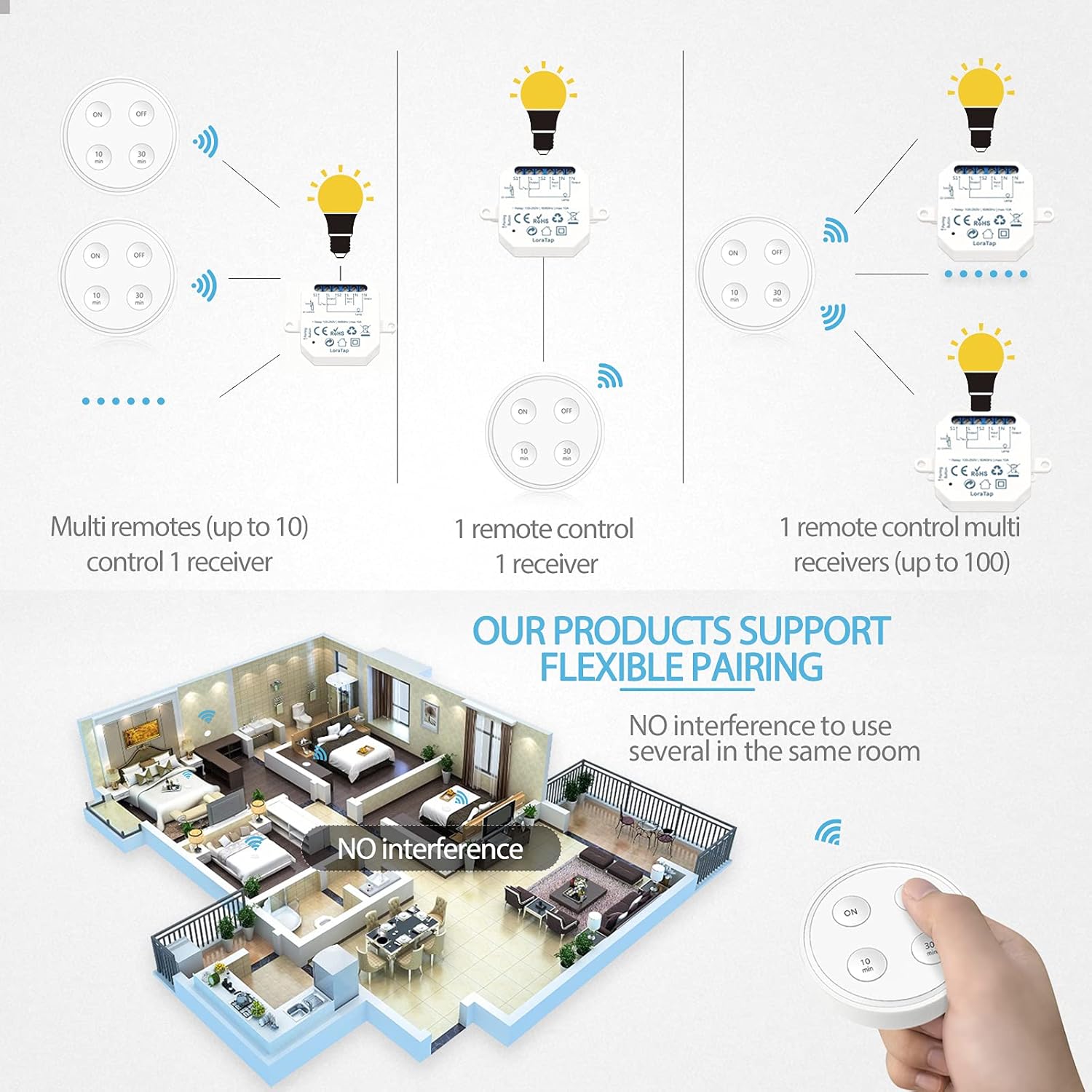
Figure 5: Flexible pairing options for LoraTap devices.
6. Operating Instructions
Use the wireless transmitter to control your connected appliance.
- ON Button: Press to turn on the connected appliance.
- OFF Button: Press to turn off the connected appliance.
- 10 min Button: Press to turn on the appliance for 10 minutes, after which it will automatically turn off.
- 30 min Button: Press to turn on the appliance for 30 minutes, after which it will automatically turn off.

Figure 6: The timing function helps prevent forgetting to turn off appliances like exhaust fans.
7. Maintenance
7.1. Battery Replacement (Transmitter)
The wireless transmitter uses a CR2032 coin cell battery. When the control range decreases or the transmitter becomes unresponsive, it may be time to replace the battery.
- Gently pry open the back cover of the transmitter.
- Remove the old CR2032 battery.
- Insert a new CR2032 battery with the positive (+) side facing up.
- Close the back cover securely.
7.2. Cleaning
Wipe the surfaces of the receiver and transmitter with a soft, dry cloth. Do not use abrasive cleaners or immerse the devices in water.
8. Troubleshooting
- Device not responding:
- Check if the receiver has power.
- Ensure the transmitter battery is not depleted. Replace if necessary.
- Re-pair the transmitter and receiver (refer to Section 5).
- Ensure the transmitter is within the effective control range.
- Intermittent control:
- Check for strong radio interference sources nearby.
- Ensure the receiver is not obstructed by large metal objects.
- Replace the transmitter battery.
- Appliance not turning on/off:
- Verify the wiring connections to the receiver module are correct and secure.
- Ensure the connected appliance is functioning correctly.
- Check if the appliance's power consumption exceeds the receiver's maximum load/power rating.
9. Specifications
| Feature | Specification |
|---|---|
| Model Number | SS1030R6-16A |
| Receiver Dimensions (L x W x H) | 4.6 x 4.6 x 1.8 cm (46 x 46 x 18 mm) |
| Transmitter Dimensions (Diameter x Thickness) | 6.8 x 1.6 cm |
| Receiver Input/Output Voltage | 100-250 VAC, 50/60 Hz |
| Maximum Current Rating | 10A |
| Maximum Power (LED/Fluorescent) | 300W |
| Maximum Power (Incandescent/Halogen/Other) | 2500W |
| Wireless Frequency | 868 MHz |
| Wireless Range (Indoor) | Up to 30 meters |
| Wireless Range (Outdoor) | Up to 200 meters |
| Transmitter Battery Type | CR2032 |
| Transmitter Lifespan | >220,000 clicks |
| Material | Acrylonitrile Butadiene Styrene (ABS) |
| Operating Mode | Manual |
| Certifications | CE, RoHS |
10. Warranty and Support
LoraTap provides a 5-year warranty for this product, covering defects in materials and workmanship under normal use. For technical support, warranty claims, or further assistance, please contact LoraTap customer service through their official website or your purchase platform.
This product is certified CE and RoHS, ensuring compliance with European safety and environmental standards.