1. Introduction
This manual provides detailed instructions for the setup, operation, maintenance, and troubleshooting of the Rakstore BU01 UWB Indoor Positioning Module DW1000 NodeMCU-BU01 Development Board. Please read this manual thoroughly before using the device to ensure proper functionality and to maximize its performance.
2. Product Overview
The Rakstore BU01 is a compact Ultra-Wideband (UWB) module designed for high-precision indoor positioning and ranging applications. It integrates the DW1000 chip and is presented as a NodeMCU-compatible development board, offering ease of integration into various projects.
Key Features:
- Frequency range: 3.5 GHz to 6.5 GHz
- Interface: PWM/I2C/GPIO, all IO of MCU
- Antenna form: PCB antenna on board
- Transmission distance: Approximately 40 meters
- Transmit power: 802.11b: 16 ± 2dbm; 802.11g: 16 ± 2dbm; 802.11n: 16 ± 2dbm
- Dimension: 35mm x 56mm
Module Components:
The BU01 development board includes the DW1000 UWB module, a micro-USB port for power and data, reset and user buttons, status LEDs, and pin headers for various I/O connections.

This image displays the top side of the Rakstore BU01 UWB Indoor Positioning Module development board. Key visible components include the central BU01 UWB module, a micro-USB port on the left for power and data communication, a reset button, and multiple pin headers along the edges for connecting to external circuits and accessing GPIOs.

This angled view provides a clearer perspective of the BU01 UWB development board, showcasing the integrated PCB antenna on the right side of the module. Various surface-mount components and integrated circuits are visible, contributing to the board's functionality.

This image presents a top-down view of the BU01 development board, clearly indicating its physical dimensions. The board measures 56mm in length and 35mm in width, providing a compact form factor for integration into projects.
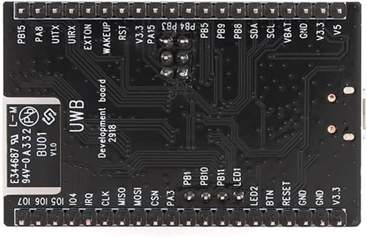
The bottom view of the BU01 development board reveals the pin labels for its various interfaces. These include GPIO pins (e.g., PB1, PB10, PA3), power pins (GND, V3.3, V5), and communication interfaces (e.g., TX, RX, SCL, SDA, MISO, MOSI, CSN, CLK, IRQ), essential for connecting the module to other components or microcontrollers.

This block diagram illustrates the internal architecture of the DW1000 IC, which is central to the BU01 module's functionality. It shows the flow from the on-board antenna through the analog receiver and transmitter, PLL/clock generator, digital transceiver, and into the power management, host interface (SPI), and state controller blocks. This diagram helps in understanding the module's operational principles and data flow.
3. Setup
3.1 Power Supply
The BU01 module can be powered via the micro-USB port or through the V3.3/V5 pins on the pin headers. Ensure a stable power supply within the specified voltage range (2.8 V to 3.6 V DC for the core DW1000 IC, typically 5V via USB or V5 pin).
3.2 Connection to Host Microcontroller
Connect the BU01 development board to your host microcontroller (e.g., Arduino, ESP32) using the appropriate GPIO pins. The primary communication interface for the DW1000 is SPI. Ensure the following connections are made:
- MISO (Master In Slave Out)
- MOSI (Master Out Slave In)
- SCK (Serial Clock)
- CSN (Chip Select Not)
- IRQ (Interrupt Request) - Optional, but recommended for efficient operation
- GND (Ground)
- VCC (3.3V or 5V depending on the host)
Refer to the pinout diagram (Figure 2.4) for specific pin locations on the BU01 board.
3.3 Software and Firmware
To utilize the BU01 module, specific firmware or software libraries are required for your host microcontroller. These typically include drivers for the DW1000 chip and example code for ranging and positioning applications. Consult the manufacturer's documentation or community resources for compatible libraries and example projects.
4. Operating Instructions
Operating the BU01 module involves programming your host microcontroller to communicate with the DW1000 chip and implement UWB ranging or positioning algorithms.
4.1 Basic Ranging
- Initialize DW1000: Use the provided library functions to initialize the DW1000 chip, setting up communication parameters and UWB channel.
- Configure as Initiator/Responder: For two-way ranging, one module acts as an initiator (sending poll messages) and the other as a responder (replying to poll messages).
- Exchange Messages: The initiator sends a poll message, the responder receives it and sends a response, and the initiator receives the response. Time-of-flight is calculated based on these timestamps.
- Calculate Distance: The time-of-flight is converted into distance using the speed of light.
4.2 Positioning Systems
For indoor positioning, multiple BU01 modules (anchors) are typically placed at known locations, and a mobile BU01 module (tag) determines its position by ranging with these anchors. Triangulation or multilateration algorithms are then used to calculate the tag's coordinates.
- Anchor Setup: Program multiple BU01 modules as anchors with fixed, known positions.
- Tag Operation: Program a mobile BU01 module as a tag to perform ranging with each anchor.
- Position Calculation: Collect distance data from multiple anchors and apply a positioning algorithm (e.g., trilateration) to determine the tag's real-time position.
5. Maintenance
The BU01 module is a robust electronic component, but proper handling and care are essential for its longevity and reliable operation.
- Environmental Conditions: Operate and store the module in a dry environment, away from extreme temperatures, humidity, and direct sunlight.
- Handling: Avoid static discharge. Handle the board by its edges to prevent damage to components.
- Cleaning: If necessary, gently clean the board with a soft, dry brush or compressed air. Avoid using liquids or harsh chemicals.
- Firmware Updates: Regularly check for and apply firmware updates for the DW1000 chip or your host microcontroller's libraries to ensure optimal performance and access to new features.
6. Troubleshooting
If you encounter issues with your BU01 module, consider the following troubleshooting steps:
- No Power/LEDs Off:
- Check power supply connections and voltage levels.
- Ensure the micro-USB cable is functional and properly connected.
- Communication Errors (SPI):
- Verify all SPI connections (MISO, MOSI, SCK, CSN) are correct and secure.
- Check for correct pin assignments in your microcontroller code.
- Ensure the SPI clock speed is compatible with the DW1000.
- Inaccurate Ranging/Positioning:
- Ensure clear line-of-sight between modules for optimal performance. Obstacles can significantly affect UWB signals.
- Verify the UWB channel and configuration settings in your firmware.
- Check for environmental interference from other wireless devices.
- Calibrate the modules if necessary, following specific library instructions.
- Module Not Detected:
- Confirm the module is receiving power.
- Check if the correct drivers or libraries are installed and initialized in your code.
- Perform a hard reset of the module using the onboard reset button.
7. Specifications
| Feature | Specification |
|---|---|
| Model Name | BU01 |
| Brand | Rakstore |
| Wireless Type | 802.11b, 802.11g, 802.11n (referring to transmit power standards) |
| Frequency Range | 3.5 GHz to 6.5 GHz (UWB) |
| Interface | PWM/I2C/GPIO, all IO of MCU |
| Antenna Form | PCB antenna on board |
| Transmission Distance | Approximately 40 meters |
| Transmit Power | 802.11b: 16 ± 2dbm; 802.11g: 16 ± 2dbm; 802.11n: 16 ± 2dbm |
| Dimension | 35mm x 56mm |
| Compatible Devices | Personal Computer, Server (as host for development) |
| Platform | Not Machine Specific |
8. Warranty and Support
For warranty information, technical support, or further inquiries regarding the Rakstore BU01 UWB Indoor Positioning Module, please refer to the official Rakstore website or contact their customer service directly. Keep your purchase receipt for any warranty claims.


