1. Introduction
The BENNING CM 2-1 is a True RMS current clamp multimeter designed for precise electrical measurements in various applications. This device offers accurate current measurement up to 400 A AC/DC and voltage measurement up to 600 V AC/DC. Key features include an AutoV function with low input impedance (LoZ) to suppress reactive voltage and a low pass filter (HFR high frequency suppression) for measurements on clocked motor drives. It is rated for measurement categories CAT IV 300 V and CAT III 600 V, ensuring safety and reliability.
2. Safety Information
WARNING: Read and understand all safety information and operating instructions before using this instrument. Failure to follow these instructions could result in severe injury or death.
- Always adhere to local and national safety regulations.
- Do not use the multimeter if it appears damaged or if the insulation on the test leads is compromised.
- Ensure the correct function and range are selected before making any measurements.
- Do not exceed the maximum input limits for any function.
- Be cautious when working with voltages above 30 V AC RMS, 42 V AC peak, or 60 V DC, as these pose a shock hazard.
- Always disconnect the test leads from the circuit before changing the function switch.
- Replace batteries when the low battery indicator appears to ensure accurate readings.
- The device is rated CAT IV 300 V and CAT III 600 V. Understand these categories and use the meter only in appropriate environments.
3. Package Contents
Verify that all items are present and undamaged upon unpacking:
- BENNING CM 2-1 True RMS Current Clamp Multimeter
- Protective carrying bag
- Set of test leads (red and black)
- 2 AAA batteries (pre-installed or included separately)

Image 3.1: The BENNING CM 2-1 multimeter shown with its protective carrying bag and test leads.
4. Product Overview
The BENNING CM 2-1 features a compact design with a clear digital display, a rotary function switch, and control buttons for various measurement modes.
4.1. Controls and Display
- Clamp Jaw: For non-contact AC/DC current measurement.
- Rotary Switch: Selects measurement functions (OFF, LoZ, AutoV, V~, V-, Hz, Ω, A~, A-).
- HOLD/MIN MAX Button: Freezes the current reading or displays minimum/maximum values.
- AC/DC HFR/ZERO Button: Toggles between AC/DC current, activates the low pass filter (HFR), or zeros the DC current reading.
- Display: Digital readout for measurement values, units, and indicators.
- Input Jacks (COM, VΩ): For connecting test leads for voltage, resistance, and other measurements.
5. Setup
5.1. Battery Installation
The BENNING CM 2-1 requires 2 AAA batteries. These are typically included with the device.
- Ensure the multimeter is turned OFF.
- Locate the battery compartment on the rear of the device.
- Use a screwdriver to open the battery compartment cover.
- Insert the 2 AAA batteries, observing the correct polarity (+/-) as indicated inside the compartment.
- Replace the battery compartment cover and secure it with the screw.
6. Operating Instructions
6.1. AC/DC Current Measurement (Clamp)
To measure AC or DC current without breaking the circuit:
- Turn the rotary switch to the “A~” or “A-” position.
- Press the AC/DC HFR/ZERO button to select AC or DC current if necessary. For DC current, press and hold to zero the display before measurement.
- Open the clamp jaw and enclose a single conductor. Ensure the jaw is fully closed.
- Read the current value on the display.
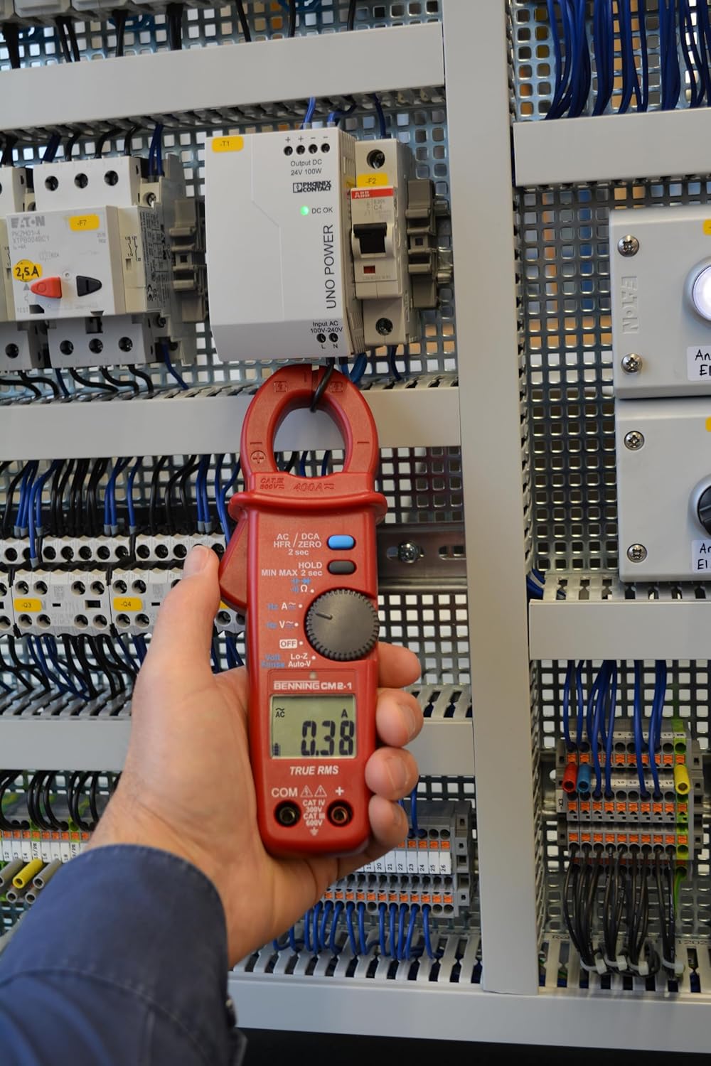
Image 6.1: The multimeter measuring current by clamping around a single conductor in an electrical panel.
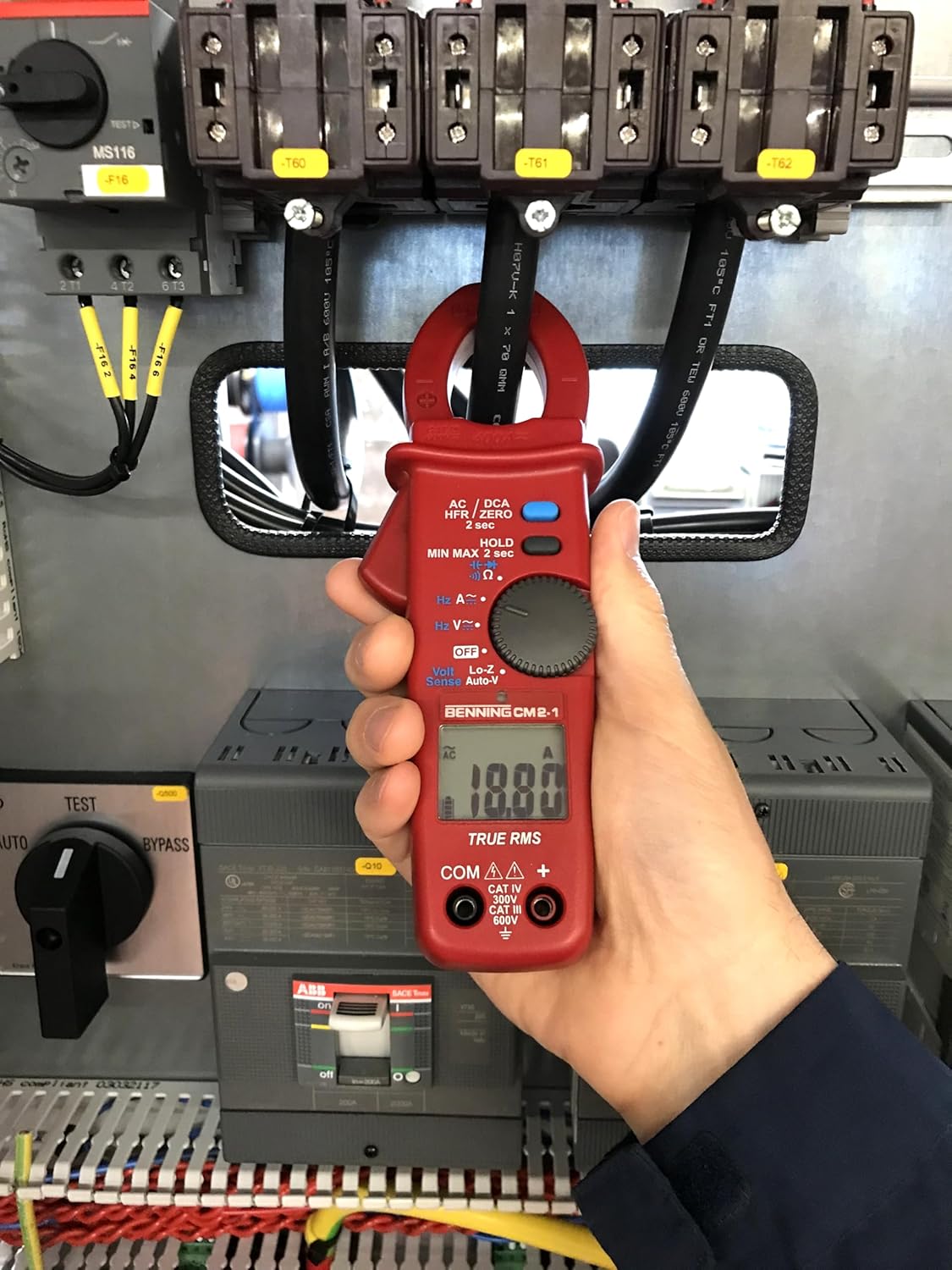
Image 6.2: A close-up of the BENNING CM 2-1 displaying a current measurement of 10.07 A.
6.2. AC/DC Voltage Measurement
To measure AC or DC voltage:
- Insert the red test lead into the VΩ jack and the black test lead into the COM jack.
- Turn the rotary switch to the “V~” for AC voltage or “V-” for DC voltage.
- Connect the test probes across the circuit or component to be measured.
- Read the voltage value on the display.

Image 6.3: The multimeter measuring voltage using test leads connected to terminals within an electrical cabinet.

Image 6.4: A close-up of the BENNING CM 2-1 displaying a voltage measurement of 124.00 V.
6.3. AutoV Function (LoZ)
The AutoV function with low input impedance (LoZ) helps to suppress 'ghost voltages' or 'reactive voltages' that can appear on unused wires or open circuits due to capacitive coupling. To use:
- Insert the red test lead into the VΩ jack and the black test lead into the COM jack.
- Turn the rotary switch to the “LoZ” position. The meter will automatically detect AC or DC voltage.
- Connect the test probes across the circuit.
- Read the voltage value on the display.
6.4. Low Pass Filter (HFR)
The HFR (High Frequency Rejection) low pass filter is used for stable and accurate measurements on variable frequency drives (VFDs) or other noisy electrical environments. To activate:
- Select the desired AC current (A~) or AC voltage (V~) function.
- Press and hold the AC/DC HFR/ZERO button until “HFR” appears on the display.
- Proceed with your measurement as usual. The filter will suppress high-frequency noise components.
7. Maintenance
7.1. Cleaning
Wipe the case with a damp cloth and mild detergent. Do not use abrasives or solvents. Ensure the device is completely dry before use.
7.2. Battery Replacement
When the low battery indicator appears on the display, replace the batteries promptly to ensure continued accurate operation. Refer to Section 5.1 for battery installation instructions.
8. Troubleshooting
- No Display: Check battery installation and charge. Replace batteries if necessary.
- Incorrect Readings: Ensure correct function and range are selected. Check test lead connections. Verify the clamp jaw is fully closed for current measurements.
- “OL” on Display: Indicates an overload (measurement exceeds the selected range). Select a higher range or ensure the input is within the device's specifications.
- Unstable Readings: Ensure good contact with test probes. For current measurements, ensure only one conductor is within the clamp jaw. Consider using the HFR function in noisy environments.
9. Specifications
| Specification | Value |
|---|---|
| Manufacturer | BENNING |
| Model Number | 044689 |
| Item Weight | 480 g |
| Product Dimensions (L x W x H) | 17 x 5 x 13 cm |
| Batteries | 2 AAA batteries (included) |
| Battery Cell Type | Alkaline |
| Colour | Red |
| Style | Digital |
| Power Source Type | Battery Powered |
| Measurement Type | Multimeter (True RMS) |
| Max. AC/DC Current | 400 A |
| Max. AC/DC Voltage | 600 V |
| Measurement Category | CAT IV 300 V, CAT III 600 V |
| Safety Standard | EN 61010-1 |
| Included Components | Benning CM 2-1, bag, test leads, batteries |
10. Warranty and Support
BENNING products are manufactured to high-quality standards. For specific warranty information, please refer to the documentation provided with your purchase or visit the official BENNING website. For technical support, service, or inquiries, please contact your local BENNING distributor or customer service department.