1. Introduction
This manual provides comprehensive instructions for the installation, operation, and maintenance of the Acogedor A2-8075 Variable Frequency Drive (VFD). The A2-8075 is designed to control the speed and torque of AC induction motors, offering precise control and energy efficiency for various industrial applications.
Please read this manual thoroughly before operating the device to ensure safe and efficient use.
2. Safety Instructions
WARNING: High Voltage Inside.
- Do not connect AC power to output terminals (U, V, W).
- Discharging time is greater than 5 seconds. Wait at least 5 seconds after power-off before touching terminals.
- Do not inspect components unless the "CHARGE" lamp is turned OFF.
- Only qualified personnel should install, operate, and maintain this VFD.
- Ensure proper grounding to prevent electric shock.
- Disconnect all power sources before performing any wiring or maintenance.

Figure 1: Front view of the Acogedor A2-8075 VFD, highlighting the control panel and the "High Voltage Inside" warning label.
3. Product Features
- Made of industrial flame-retardant ABS material, ensuring heat resistance, flame retardancy, impact resistance, and safety.
- Equipped with common functions of current mainstream inverters, offering comprehensive functionality for various scenarios.
- Humanized keyboard design for easy operation and clear display.
- Super large all-aluminum base fan heater combined with an imported powerful fan for superior wind power and rapid heat dissipation.

Figure 2: Side view of the VFD, illustrating its robust design suitable for industrial applications.
4. Technical Specifications
| Parameter | Value |
|---|---|
| Model Name | A2-8075 |
| Input Voltage | Single Phase AC 180-250V |
| Output Voltage | 3 Phase 220V |
| Power | 7.5 KW |
| Item Weight | 6.52 pounds (approx. 2.96 kg) |
| Package Dimensions | 10.71 x 9.25 x 7.87 inches (approx. 27.2 x 23.5 x 20 cm) |
| Color | Black |
| Material | Industrial Flame-retardant ABS |

Figure 3: Physical dimensions of the A2-8075 VFD, showing height, depth, and width measurements.
5. Setup and Installation
5.1. Unpacking and Inspection
Upon receiving the VFD, carefully unpack it and inspect for any signs of damage during transit. Report any damage to your supplier immediately.
5.2. Mounting
Mount the VFD vertically on a flat, stable surface in an environment that meets the specified operating conditions (temperature, humidity, ventilation). Ensure adequate clearance for heat dissipation, especially around the cooling fins and fan.
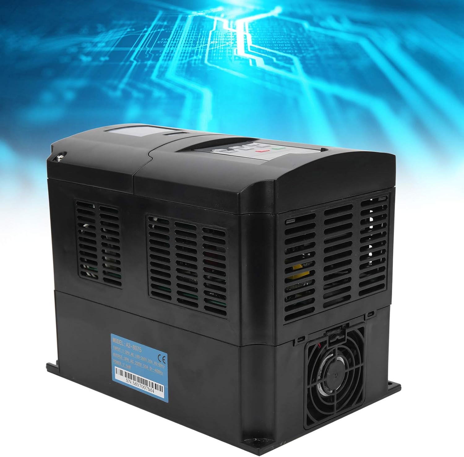
Figure 4: Side view of the VFD, illustrating the cooling vents essential for proper heat dissipation during operation.
5.3. Wiring
All wiring must be performed by a qualified electrician in accordance with local and national electrical codes.
- Power Input (R, T): Connect the single-phase AC 180-250V power supply to the R and T terminals.
- Motor Output (U, V, W): Connect the three-phase motor to the U, V, and W terminals. Ensure correct phase sequence for desired motor rotation.
- Grounding (PE): Connect the protective earth (ground) terminal to a reliable ground point. This is crucial for safety.
- Control Terminals: Refer to the detailed wiring diagram (not provided in this manual, refer to product specific documentation) for connecting external control signals (e.g., start/stop, speed reference, fault indicators).
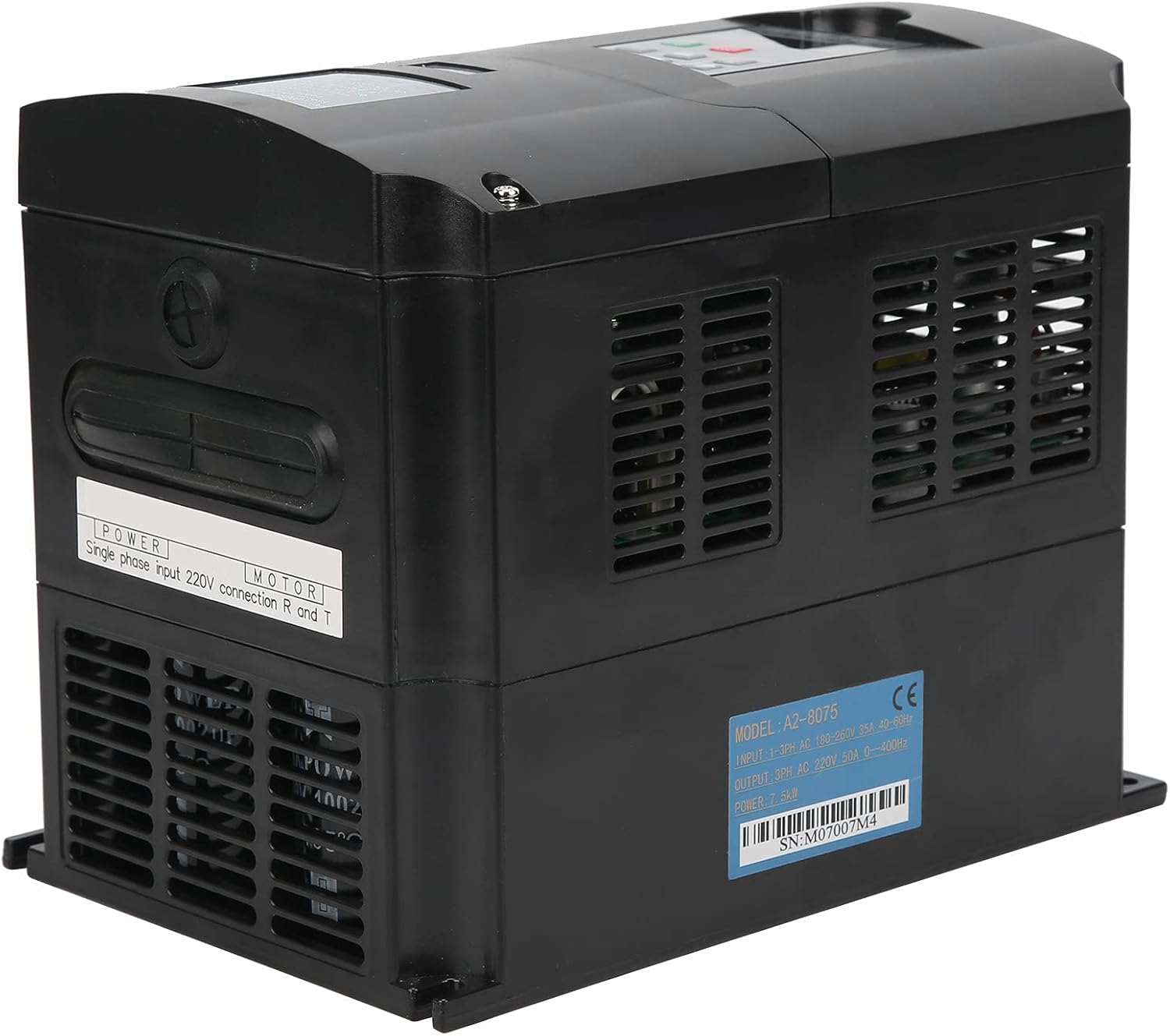
Figure 5: Rear/side view of the VFD, showing the label with model number A2-8075 and serial number SN:M07007M4. This label provides critical information for wiring and identification.
The serial number for this unit is M07007M4.
6. Operating Instructions
6.1. Control Panel Overview
The VFD features a user-friendly control panel for direct operation and parameter setting.

Figure 6: Close-up view of the VFD's control panel, detailing the display and button layout.
- Digital Display: Shows operating frequency, output current, voltage, and various parameter values.
- RUN/STOP Button (Green): Initiates or stops motor operation.
- STOP/RESET Button (Red): Stops motor operation and resets any active fault conditions.
- SET Button: Enters parameter setting mode or confirms parameter changes.
- Up/Down Arrows: Navigate through parameters or adjust values.
- REV/FWD Button: Changes the direction of motor rotation (Reverse/Forward).
- JOG Buttons: Provides momentary motor operation for testing or precise positioning.
6.2. Basic Operation
- Power On: Ensure all wiring is correct and secure. Apply single-phase AC power to the VFD. The digital display will light up.
- Set Frequency (if needed): Use the SET button and arrow keys to adjust the desired output frequency. Refer to the full parameter list in the detailed product manual for specific parameter codes.
- Start Motor: Press the RUN/STOP button to start the motor. The display will show the current operating frequency.
- Change Direction: Press the REV/FWD button to reverse the motor's direction of rotation.
- Stop Motor: Press the STOP/RESET button to stop the motor.
7. Maintenance
Regular maintenance ensures the longevity and optimal performance of your VFD. Always disconnect power before performing any maintenance.
- Cleaning: Periodically clean the VFD's exterior, especially the cooling fins and fan, to prevent dust accumulation that can hinder heat dissipation. Use a soft, dry cloth. Do not use liquid cleaners.
- Fan Inspection: Check the cooling fan for proper operation and any unusual noises. Replace if necessary.
- Terminal Tightness: Annually check all wiring terminals for tightness. Loose connections can cause overheating and malfunction.
- Environmental Check: Ensure the operating environment remains within specified temperature and humidity ranges.
8. Troubleshooting
This section provides solutions to common issues. For complex problems, contact technical support.
| Problem | Possible Cause | Solution |
|---|---|---|
| VFD does not power on | No input power; Blown fuse; Internal fault | Check power supply; Check fuses; Contact support if fault persists |
| Motor does not run | Incorrect wiring; Parameter settings incorrect; Overload; Fault condition | Verify wiring (U, V, W); Check parameter settings; Reduce load; Check for fault codes on display and reset |
| Overheat alarm | Poor ventilation; Clogged fan/fins; Ambient temperature too high; Overload | Ensure proper airflow; Clean fan/fins; Reduce ambient temperature; Reduce load |
| Motor runs in wrong direction | Incorrect phase sequence; REV/FWD button pressed | Swap any two motor output phases (U, V, W); Press REV/FWD button again |
9. Warranty and Support
For warranty information and technical support, please refer to the documentation included with your purchase or contact Acogedor customer service. You can also visit the official Acogedor Store on Amazon for more product information.


