Product Overview
The GDAE10 ITX ATX MATX PC Motherboard Case Frame is an open bare metal test bench designed for air and water cooling setups. It supports various motherboard sizes and offers efficient heat dissipation for overclocking and testing environments.

Image: The fully assembled GDAE10 ITX ATX MATX PC Motherboard Case Frame, showcasing its open design and red aluminum profiles.
Key Features
- Chassis Material: 20x20 Aluminum Profile / Acrylic Accessories
- Applicable Motherboard: ITX (17 x 17cm), M-ATX, ATX Motherboard
- Extended Hard Drive Positions: 1x 3.5-inch, 1x 2.5-inch
- PCI Expansion Slots: 7
- Switch Interface: Start / Restart Switch and Indicator
Package Contents
Before beginning assembly, please verify that all components listed below are present in your package. Refer to the provided diagrams for visual identification.

Image: All individual components of the PC Motherboard Case Frame, including aluminum profiles, acrylic panels, screws, and cables, neatly arranged on a surface.
- Aluminum Profiles (various lengths)
- Acrylic Motherboard Tray
- Acrylic Side Panels
- PCI Expansion Slot Bracket
- Power/Reset Switch with Cable
- Hard Drive Brackets
- Corner Fittings and T-Shaped Fittings
- Assorted Screws, Nuts, and Washers
- Allen Wrench
- Self-adhesive Non-slip Pads
- Gloves (for handling components)
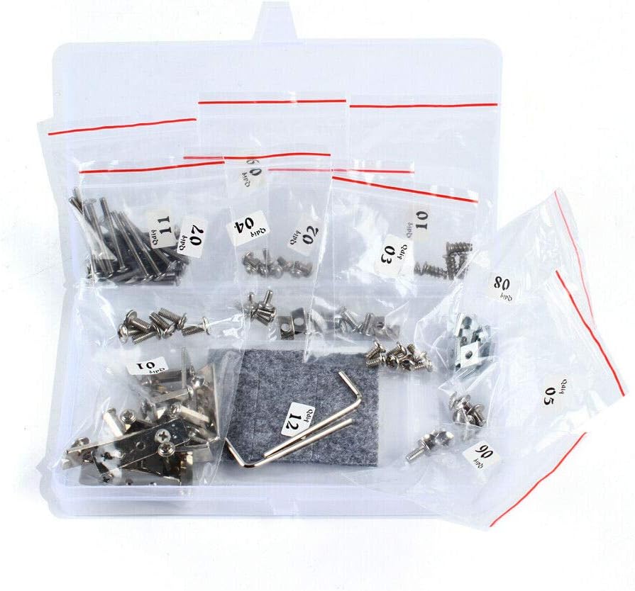
Image: A close-up view of various screws, nuts, and small metal components, organized in plastic bags, essential for assembling the frame.
Setup and Installation
This section guides you through the assembly of the GDAE10 PC Motherboard Case Frame and the installation of your computer components. Please follow the steps carefully. Wearing gloves is recommended to prevent fingerprints and scratches on acrylic parts.
Video Guide: Detailed Installation
Video: A comprehensive installation guide for the ITX ATX MATX PC Motherboard Case Frame, demonstrating each step of assembly and component mounting.
Step-by-Step Assembly
- Frame Base Assembly:
Begin by assembling the base of the frame using the aluminum profiles and corner fittings. Ensure all screws are tightened with the provided Allen wrench for stability.

Image: Detailed view of the metal corner fittings and screws, illustrating how they connect the aluminum profiles to form the frame structure.
- Motherboard Tray Installation:
Attach the acrylic motherboard tray to the assembled frame. Use the specified screws and nuts to secure it firmly. The tray has pre-drilled holes for various motherboard sizes (ITX, M-ATX, ATX).

Image: The clear acrylic motherboard tray, showing multiple mounting points for different motherboard form factors.
- Power/Reset Switch Installation:
Mount the power and reset switch onto one of the acrylic side panels or a designated location on the frame. Connect the switch cables to your motherboard's front panel headers.

Image: The power and reset switch, featuring a durable braided cable, ready for installation onto the frame.
- Hard Drive and SSD Mounting:
Install your 3.5-inch hard drives and 2.5-inch SSDs using the provided brackets and screws. Secure them to the designated mounting points on the frame.
- Power Supply Unit (PSU) Installation:
Mount your power supply unit to the bottom section of the frame. Ensure it is securely fastened and cables are routed neatly.
- Motherboard and Component Installation:
Carefully place your motherboard onto the acrylic tray, aligning it with the standoffs. Secure the motherboard with screws. Install your CPU, RAM, and any other essential components onto the motherboard.
- Graphics Card Installation:
Insert your graphics card(s) into the PCI-E slots on the motherboard. Secure the graphics card(s) to the PCI expansion slot bracket using screws.
- Cooling Fan Installation:
If using additional cooling fans, attach them to the designated fan mounting points on the frame. Ensure proper airflow direction for optimal cooling.
- Cable Management:
Organize all power and data cables to maintain a clean setup and prevent interference with airflow. Use cable ties or clips if necessary.
Supplementary Video Guide
Video: A concise installation guide for the ITX ATX MATX PC Motherboard Case, providing an overview of the assembly process.
Operating Instructions
Once all components are securely installed and cables are connected, you can power on your system.
- Connect your monitor, keyboard, and mouse to the motherboard's I/O ports.
- Connect the power cable to the PSU and a wall outlet.
- Press the power button on the frame to start your computer.
- Use the reset button if your system becomes unresponsive and requires a restart.
Maintenance
Regular maintenance helps ensure the longevity and optimal performance of your open PC case frame.
- Dust Removal: Due to the open design, dust accumulation can occur more rapidly. Regularly use compressed air to clean dust from components, especially fans and heatsinks.
- Acrylic Panel Care: Some acrylic panels are one-off designs. Handle them with care. To maintain clarity and prevent scratches, clean acrylic panels with a soft, lint-free cloth and a mild, non-abrasive cleaner. Avoid harsh chemicals.
- Screw Tightness: Periodically check all screws and fittings to ensure they remain tight. Vibrations from fans or other components can sometimes loosen connections.
- Cable Inspection: Inspect cables for any signs of wear or damage. Replace any damaged cables immediately.
Troubleshooting
If you encounter issues with your PC Motherboard Case Frame, consider the following common troubleshooting steps:
- System Not Powering On:
- Verify all power connections to the motherboard, CPU, and graphics card.
- Ensure the power supply is switched on.
- Check the front panel power switch connection to the motherboard.
- Component Not Detected:
- Reseat the component (RAM, GPU, storage drive) to ensure it is properly seated in its slot.
- Check power and data cable connections for storage drives.
- Overheating:
- Ensure all cooling fans are operating correctly and are free from obstructions.
- Verify CPU cooler installation and thermal paste application.
- Loose Parts:
If any parts feel loose after assembly, re-tighten the corresponding screws. Avoid over-tightening acrylic components to prevent cracking.
Specifications
| Feature | Detail |
|---|---|
| Brand | GDAE10 |
| Series | GDAE10 ITX (17 x 17cm) ATX MATX PC Motherboard Case Frame |
| Chassis Material | 20x20 Aluminum Profile / Acrylic Accessories |
| Applicable Motherboard | ITX (17 x 17cm), M-ATX, ATX Motherboard |
| Extended Hard Drive Positions | 1x 3.5-inch, 1x 2.5-inch |
| PCI Expansion Slots | 7 |
| Switch Interface | Start / Restart Switch and Indicator |
| Item Weight | 4.29 pounds |
| Package Dimensions | 13.5 x 6.69 x 3.23 inches |
| Color | ITX ATX MATX Vertical Red |
| Material | Aluminum |
| Power Supply Mounting Type | Bottom Mount |
| Cooling Method | Air |
| Recommended Uses For Product | Gaming |
| Fan Size | 17 Centimeters |
Warranty and Support
For warranty information or technical support, please contact GDAE10 customer service through the retailer where the product was purchased. Keep your proof of purchase for warranty claims.


