1. Introduction
This manual provides essential information for the safe and effective use of the Acxico DC-DC 8-32V to 45-390V High Voltage Boost Converter ZVS Step-up Booster Module. Please read these instructions carefully before installation and operation to ensure proper functionality and to prevent damage to the module or connected equipment.
2. Safety Information
WARNING: This module generates high voltage (up to 390V). Improper handling can result in severe injury or death. Always exercise extreme caution when working with high voltage circuits.
- Ensure all power is disconnected before making any connections or adjustments.
- Use appropriate insulation and safety equipment.
- Do not touch exposed terminals or components when the module is powered.
- Verify correct wiring polarity before applying power. Reverse polarity can damage the module (non-self-healing fuse).
- Ensure adequate heat dissipation, especially during high power operation, to prevent overheating.
- This module is intended for experienced users familiar with electronics and high voltage safety procedures.
3. Product Overview
The Acxico DC-DC Boost Converter is a non-isolated step-up module designed to convert a lower DC input voltage (8-32V) into a higher, continuously adjustable DC output voltage (45-390V). It features built-in protection mechanisms for short circuit, over current, and over voltage conditions.
Key Features:
- Non-isolated step-up module.
- Wide input voltage range: 8V to 32V DC.
- Adjustable output voltage: +45V to 390V DC.
- Maximum output power: 40W (Peak 70W).
- Operating frequency: 75 KHz.
- Protection features: Short circuit, over current, over voltage, and input reverse polarity (fuse protected).
- Compact design with integrated heatsink.
Component Identification:
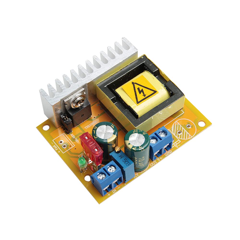
Refer to Figure 1 for the location of key components:
- 8~32V Input Terminals: Connect your DC power source here. Observe polarity.
- +45~390V Output Terminals: Connect your load here. Observe polarity.
- Output Voltage Regulation: A multi-turn potentiometer used to adjust the output voltage.
- Fan Connectors: For connecting an external cooling fan if additional heat dissipation is required.
- Heatsink: Integrated for thermal management.
4. Specifications
| Parameter | Value |
|---|---|
| Module Properties | Non-isolated step-up module |
| Input Voltage | 8V to 32V DC (Default 10V-32V) |
| Output Voltage | +45V to 390V DC (Continuously adjustable, default ±50V) |
| Input Current | 5A Max |
| Output Current | 0.2A Max (Dependent on input/output voltage difference) |
| Output Power | 40W (Peak 70W) |
| Quiescent Current | 15mA (Increases with higher output voltage) |
| Operating Frequency | 75 KHz |
| Conversion Efficiency | Up to 88% (Dependent on input/output voltage and current) |
| Working Temperature | -40°C to +85°C |
| Short Circuit Protection | Yes |
| Over Current Protection | Yes (Output voltage reduced if input current exceeds 4.5A) |
| Over Voltage Protection | Yes (Output voltage reduced if output voltage exceeds 410V) |
| Input Reverse Polarity Protection | Yes (Non-self-healing fuse, avoid reverse connection) |
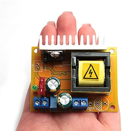
| Dimensions (L x W x H) | 60 x 50 x 20 mm (2.36 x 1.97 x 0.79 inches) |
| Weight | Approximately 60g (0.13 lbs) |

5. Setup
Follow these steps to set up your Acxico DC-DC Boost Converter module:
- Prepare Your Workspace: Ensure you have a clean, dry, and well-lit area. Gather all necessary tools, including a small screwdriver for the terminal blocks.
- Identify Terminals: Locate the input (8~32V) and output (+45~390V) screw terminals on the module as shown in Figure 1.
- Input Connection:
- Connect your DC power source (8V to 32V) to the input terminals.
- Ensure correct polarity: connect the positive (+) terminal of your power source to the '+' input terminal on the module, and the negative (-) terminal to the '-' input terminal.
- Tighten the screw terminals securely to prevent loose connections.
- Output Connection:
- Connect your load (the device requiring high voltage) to the output terminals.
- Ensure correct polarity: connect the positive (+) terminal of your load to the '+' output terminal on the module, and the negative (-) terminal to the '-' output terminal (GND).
- Tighten the screw terminals securely.
- Heat Dissipation: The module includes an integrated heatsink. For continuous operation at higher power levels or in environments with high ambient temperatures, consider connecting an external cooling fan to the designated fan connectors to enhance heat dissipation.
- Initial Voltage Adjustment (Optional but Recommended): Before connecting a sensitive load, it is recommended to power the module and adjust the output voltage to a safe, low level using the voltage regulation potentiometer. Use a multimeter to measure the output voltage.
6. Operating Instructions
Once the module is correctly wired and safety precautions are observed, you can begin operation:
- Apply Input Power: Connect your DC power source to the input terminals. The module should power on.
- Adjust Output Voltage: Use a small screwdriver to carefully turn the multi-turn potentiometer labeled "Output Voltage Regulation" (refer to Figure 1).
- Turn clockwise to increase the output voltage.
- Turn counter-clockwise to decrease the output voltage.
- Continuously monitor the output voltage with a multimeter while adjusting to reach your desired voltage between +45V and 390V.
- Monitor Performance: Observe the module's temperature during operation. If it becomes excessively hot, reduce the load or improve heat dissipation.
- Power Down: To turn off the module, disconnect the input power source.
Typical Applications:
- High voltage power supply for electronic devices.
- Capacitor charging circuits.
- Experimental setups requiring adjustable high DC voltage.
- Specialized applications such as pressure testing or pest control devices.
7. Maintenance
The Acxico Boost Converter module is designed for reliable operation with minimal maintenance. However, following these guidelines can prolong its lifespan:
- Keep Clean: Ensure the module is free from dust, dirt, and moisture. Use a soft, dry brush or compressed air to clean the heatsink and PCB periodically.
- Thermal Management: Regularly check that the heatsink is not obstructed. If operating in high-temperature environments or at peak power, ensure any connected cooling fan is functioning correctly.
- Inspect Connections: Periodically check all wiring connections for tightness and signs of wear or corrosion.
- Storage: When not in use, store the module in a dry, cool environment, away from direct sunlight and corrosive substances.
8. Troubleshooting
If you encounter issues with your module, refer to the following common problems and solutions:
| Problem | Possible Cause | Solution |
|---|---|---|
| No output voltage / Module not powering on |
|
|
| Output voltage is lower than expected or fluctuates |
|
|
| Module overheating |
|
|
9. Support
For any questions or issues not covered in this manual, please contact Acxico customer support. When contacting support, please provide details about your setup, the problem encountered, and any troubleshooting steps you have already taken. Providing pictures of your setup can also be helpful.
We appreciate your purchase and are committed to providing assistance.