1. Introduction
This manual provides essential information for the safe and efficient operation of your POWLAND 3000W Solar Inverter. This pure sine wave inverter, equipped with a built-in 60A MPPT controller, is designed for off-grid solar systems, suitable for homes, RVs, and compatible with various battery types including Lithium, Lead-Acid, AGM, Gel, and Flooded batteries. Please read this manual thoroughly before installation and use, and retain it for future reference.
2. Safety Information
Always observe the following safety precautions to reduce the risk of electric shock, fire, or injury:
- Installation must be performed by qualified personnel.
- Ensure all wiring is correctly sized and properly insulated.
- Disconnect all power sources (solar panels, battery, AC input) before performing any maintenance or wiring.
- Do not operate the inverter if it is damaged or appears to be malfunctioning.
- Keep the inverter away from flammable materials, moisture, and direct sunlight.
- Ensure adequate ventilation around the inverter to prevent overheating.
- The inverter can only work when the solar panel and the battery are connected at the same time.
3. Product Overview
The POWLAND 3000W Solar Inverter is an all-in-one unit integrating a pure sine wave inverter, a 60A MPPT solar charge controller, and a battery charger. It features an LCD screen and three LED indicators for dynamic display of system data and operating status.

Front view of the POWLAND 3000W Solar Inverter, showing the LCD display and control buttons.

Key features of the 3KW Solar Inverter, highlighting 60A Max Solar Charge Current, 3000W Rated Power, and 100VDC Max PV Voltage.
3.1. MPPT Charge Controller
The inverter utilizes advanced Maximum Power Point Tracking (MPPT) technology to optimize power extraction from the solar photovoltaic (PV) array. This ensures maximum efficiency, up to 99%, by tracking the peak power point of the PV array in varying environmental conditions.

Graph illustrating the MPPT Peak Point versus PWM Power Point for solar charge controllers.
4. Setup and Installation
Proper installation is crucial for the safe and efficient operation of your inverter. Follow these steps carefully:
4.1. Site Selection
- Install the inverter indoors, in a cool, dry, and well-ventilated area.
- Avoid direct sunlight, high temperatures, and high humidity.
- Ensure sufficient clearance around the inverter for proper airflow.
4.2. Wiring Connections
Refer to the connection diagram below for proper wiring. Ensure all connections are secure and polarity is correct.

Detailed connection diagram for the POWLAND Solar Inverter, showing connections for solar panels, battery, mains power/generator, and home loads.
- Battery Connection: Connect the 24V battery bank to the inverter's battery terminals. Ensure correct polarity (positive to positive, negative to negative). The inverter supports 24V Lead-Acid (seal, AGM, Gel, Flooded) and Lithium batteries.
- Solar Panel Connection: Connect your solar panel array to the PV input terminals. Ensure the PV open circuit voltage does not exceed 100 Vdc and the operating voltage range is 30-100 Vdc. Max 1600W input.
- AC Input Connection: Connect the mains power or generator to the AC input terminals. Input Voltage Range: 90~140Vac.
- AC Output Connection: Connect your household appliances or home loads to the AC output terminals. The inverter provides 110V-120V AC, 50Hz/60Hz frequency (auto detection), with a maximum output of 3000W.
Note: The off-grid inverter requires both solar panels and a battery connected simultaneously to function.
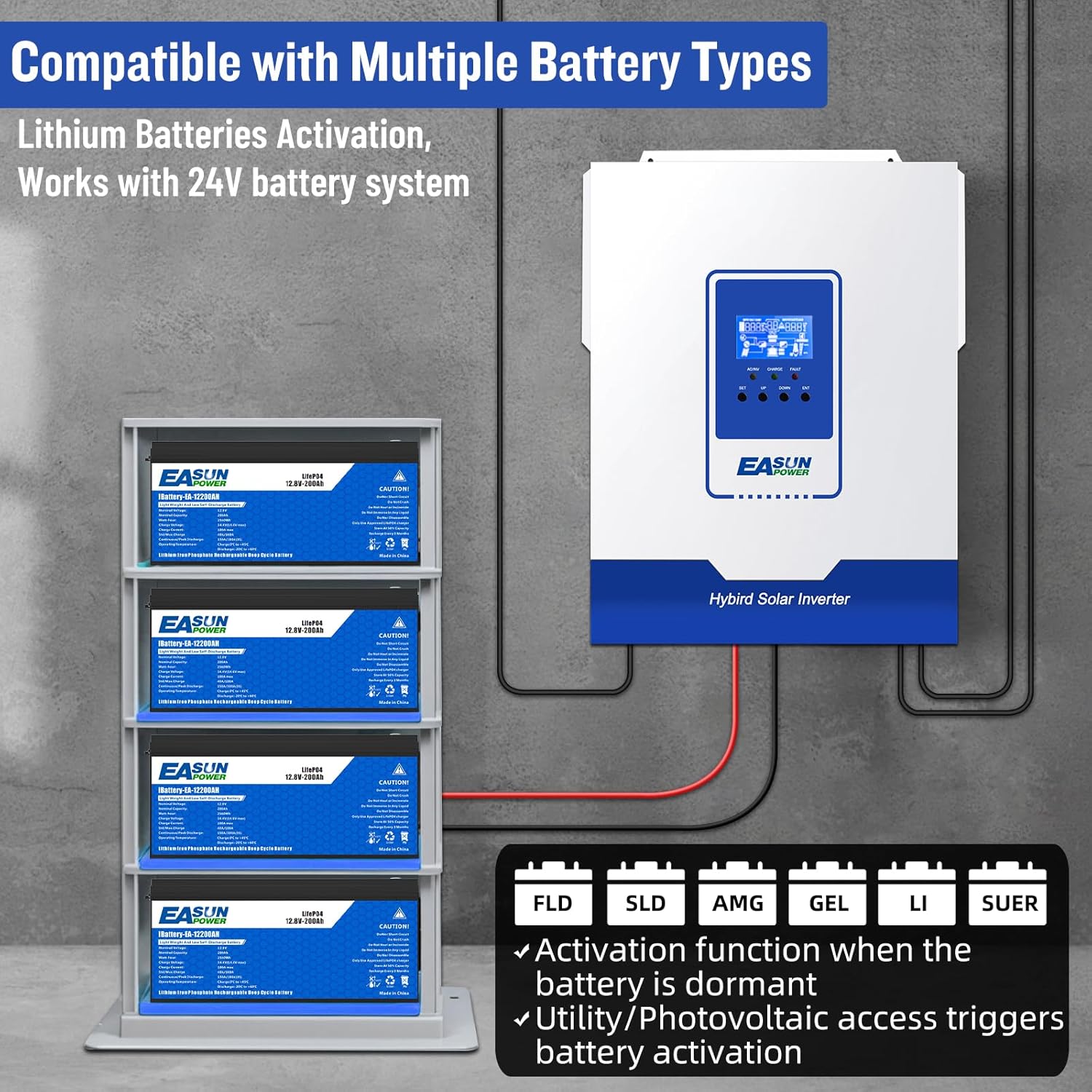
The inverter is compatible with various battery types including FLD (Flooded), SLD (Sealed Lead-Acid), AMG (AGM), GEL, and LI (Lithium) batteries, working with 24V battery systems.
5. Operating Instructions
The inverter offers multiple working modes and output options to suit various power needs.
5.1. Charging Modes
The inverter supports four charging modes:
- Only Solar: Charges batteries exclusively from solar panels.
- Mains Priority: Charges batteries primarily from the utility grid, with solar as a secondary source.
- Solar Priority: Charges batteries primarily from solar panels, with the utility grid as a secondary source.
- Mains & Solar Hybrid Charging: Utilizes both mains and solar power for battery charging.
5.2. Output Modes
The inverter provides two output modes:
- Mains Bypass: AC loads are powered directly from the utility grid.
- Inverter Output: AC loads are powered by the inverter from the battery bank.
5.3. LCD Display and Indicators
The LCD screen displays real-time system data, while three LED indicators provide quick status updates:
- AC/INV: Indicates AC input or inverter output status.
- CHARGE: Indicates battery charging status.
- FAULT: Indicates system fault or error.
5.4. Appliance Compatibility
The pure sine wave output ensures compatibility with a wide range of household appliances, power tools, industrial equipment, and electronic audio/video equipment.

The inverter is compatible with common household appliances such as microwaves, blenders, electric kettles, refrigerators, and air conditioners.
6. Maintenance
Regular maintenance helps ensure the longevity and optimal performance of your inverter.
- Cleaning: Keep the inverter clean and free from dust. Use a dry cloth to wipe the exterior. Do not use liquid cleaners.
- Ventilation: Ensure ventilation openings are clear and not obstructed. Periodically check for dust buildup in the vents.
- Connections: Periodically check all wiring connections for tightness and signs of corrosion. Re-tighten if necessary.
- Battery Health: Monitor battery voltage and health according to battery manufacturer guidelines.
- Environmental Check: Ensure the operating environment remains within specified temperature and humidity ranges.
7. Troubleshooting
This section addresses common issues you might encounter with your inverter.
| Problem | Possible Cause | Solution |
|---|---|---|
| Inverter does not power on | Low battery charge; Battery not connected; Solar panels not connected; Main power switch off. | Charge batteries; Ensure battery and solar panel connections are secure; Turn on main power switch. |
| No AC output | Overload; Short circuit; Over-temperature; Battery voltage too low/high; Inverter fault. | Reduce load; Check for short circuits; Allow inverter to cool down; Check battery voltage; Consult support if fault persists. |
| PV Overvoltage error | Solar panel array voltage exceeds inverter's maximum PV input voltage (100Vdc). | Reconfigure solar panel array to reduce voltage (e.g., fewer panels in series); Ensure correct panel selection. |
| Inverter randomly stops supplying AC power | Intermittent connection; Internal fault; Battery management system (BMS) triggering shutdown. | Check all connections; Monitor system logs if available; Perform a factory reset if possible; Consult technical support. |
For issues not listed here or if problems persist, please contact customer support.
8. Specifications
| Feature | Specification |
|---|---|
| Model | MLV-3K |
| Rated Power | 3000W |
| Battery Voltage | 24VDC |
| AC Output Voltage | 110V/120V AC |
| AC Output Frequency | 50Hz/60Hz (Auto detection) |
| Waveform | Pure Sine Wave |
| Max PV Open Circuit Voltage | 100 Vdc |
| PV Operating Voltage Range | 30-100 Vdc |
| MPPT Voltage Range | 30-85Vdc |
| Max PV Input Power | 1600W |
| Max Solar Charge Current | 60A |
| Product Dimensions | 17.1 x 14.1 x 7.4 inches |
| Item Weight | 18.04 pounds |
For detailed PV module selection, refer to the table below:
| INVERTER MODEL | iSolar MLV 3KW-U |
|---|---|
| Maximum output power | 1600W |
| Maximum PV open circuit voltage | 100VDC |
| Maximum charge current | 60A |
| Maximum Power (Pmax) | 250W |
| Max.Power Voltage Vmpp(V) | 36V |
| Max.Power Current Impp(A) | 8.3A |
| Open Circuit Voltage Voc(V) | 40V |
| Short Circuit Current Isc(A) | 8.9A |
When selecting proper PV modules, ensure the Open Circuit Voltage (Voc) of PV modules does not exceed the max. PV array open circuit voltage of the inverter (100Vdc). The PV operating voltage (Vmpp) should be higher than the minimum battery voltage.
9. Warranty and Support
POWLAND products are designed for reliability and performance. For specific warranty terms and conditions, please refer to the warranty card included with your product or contact the manufacturer directly. Keep your purchase receipt as proof of purchase.
9.1. Technical Support
If you encounter any issues or have technical questions regarding your POWLAND 3000W Solar Inverter, please reach out to our customer support team. Provide your product model and a detailed description of the issue for prompt assistance.
For the latest support information and resources, please visit the official POWLAND website or contact your authorized dealer.