1. Introduction
The Essl SA-32 is a robust single-door access control system designed for secure entry management. It supports multiple access methods including proximity card, PIN, or a combination of both. This manual provides essential information for the proper installation, operation, and maintenance of your SA-32 device.
Key Features:
- User Capacity: Up to 1000 users (Card and PIN)
- Access Modes: Card, PIN, Card + PIN
- Connectivity: Wired
- Outputs: 1 Relay output, 1 PUSH (low) output, 1 Bell Output, 1 Alarm Output
- Inputs: 1 Door button port, 1 Doorbell port
- Programmable lock release time
2. Product Overview
Familiarize yourself with the components of the SA-32 access control unit.

Figure 1: Front Panel of Essl SA-32. This image displays the numeric keypad, the '*' and '#' keys, and the integrated card reader symbol at the top. A bell icon is also visible at the bottom.
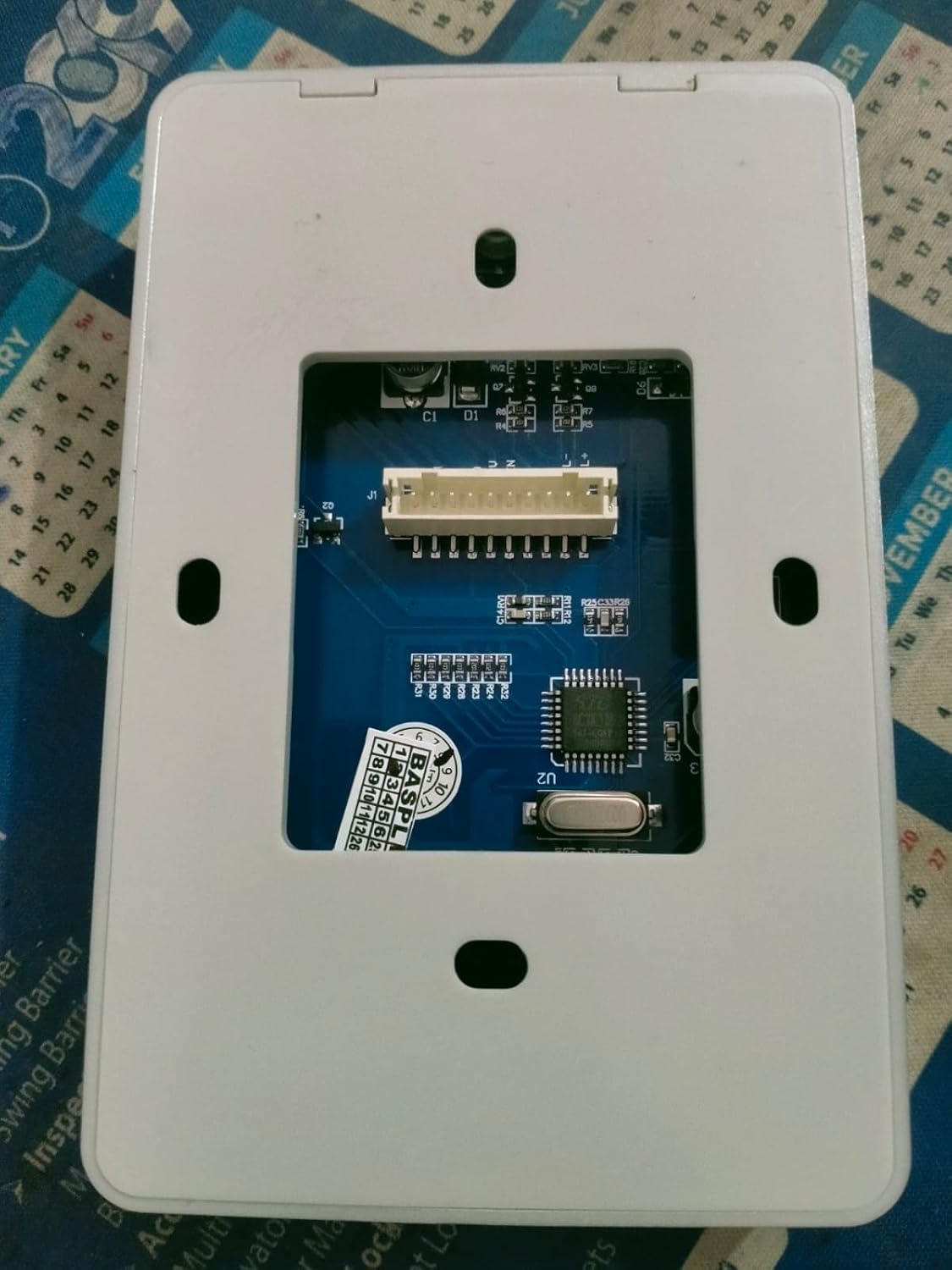
Figure 2: Back Panel of Essl SA-32. This image shows the internal circuit board with a multi-pin connector for wiring, along with mounting holes for installation.
3. Setup and Installation
Proper installation is crucial for the reliable operation of the SA-32 system. It is recommended that installation be performed by a qualified technician.
3.1 Unpacking
Carefully unpack the contents and verify that all components are present:
- Essl SA-32 Access Control Unit
- Mounting Screws and Wall Plugs (typically included)
- Wiring Harness (typically included)
- (Note: A detailed wiring diagram is essential for proper installation. Refer to the diagram provided with your unit.)
3.2 Mounting the Unit
- Choose a suitable indoor location near the door, away from direct sunlight or moisture.
- Mark the drilling points on the wall using the unit's back plate as a template.
- Drill holes and insert wall plugs.
- Secure the back plate to the wall using the provided screws.
- Attach the SA-32 unit to the secured back plate.
3.3 Wiring Connections
The SA-32 requires a 12V DC power supply. Connect the unit to your door lock, exit button, and doorbell according to the wiring diagram provided with your product. Incorrect wiring can damage the device or connected components.
Key Connections:
- Power Input: Connect to a stable 12V DC power source.
- Relay Output: Connects to the electric door lock (e.g., NO/NC contacts).
- PUSH (Low) Output: Provides a low signal for specific applications.
- Door Button Port: Connects to an external exit button.
- Doorbell Port: Connects to an external doorbell.
Important: Ensure all power is disconnected before making any wiring connections. Refer to the specific wiring diagram included with your SA-32 unit for detailed instructions.
3.4 Initial Power On
- After all wiring is complete and verified, connect the 12V DC power supply.
- The unit should power on, indicated by an LED or audible beep.
- The device will typically enter a standby mode, ready for programming.
4. Operating Instructions
This section outlines the basic operation and user management for the SA-32 access control system.
4.1 Access Modes
The SA-32 supports the following access methods:
- Card Only: Present a registered EM card to the reader.
- PIN Only: Enter a registered PIN on the keypad.
- Card + PIN: Present a registered EM card, then enter the associated PIN.
4.2 User Management (General Steps)
Note: Specific programming codes and sequences are typically found in the detailed programming manual provided with the device. The following are general steps.
Entering Programming Mode:
Usually involves entering a master code followed by a specific key (e.g., * or #).
Adding a User Card:
- Enter Programming Mode.
- Select the 'Add User Card' option (e.g., by pressing a specific number).
- Present the new EM card to the reader.
- Exit Programming Mode.
Adding a User PIN:
- Enter Programming Mode.
- Select the 'Add User PIN' option.
- Enter the desired PIN (e.g., 4-6 digits), then confirm.
- Exit Programming Mode.
Deleting Users:
Users can typically be deleted individually by card/PIN or by user ID, or all users can be reset. Refer to your specific programming manual.
4.3 Door Release
Upon successful authentication (card, PIN, or card+PIN), the SA-32 will activate its relay output for a pre-programmed duration, releasing the door lock. The door can also be opened from the inside using the connected exit button.
5. Maintenance
Regular maintenance ensures the longevity and optimal performance of your SA-32 access control system.
- Cleaning: Wipe the unit's surface with a soft, dry cloth. Avoid abrasive cleaners or solvents.
- Cable Inspection: Periodically check all wiring connections for signs of wear or damage. Ensure connections are secure.
- Functionality Test: Regularly test all access methods (card, PIN) and the exit button to ensure they are working correctly.
- Power Supply: Ensure the 12V DC power supply is stable and free from fluctuations.
6. Troubleshooting
This section addresses common issues you might encounter with the SA-32 unit.
| Problem | Possible Cause | Solution |
|---|---|---|
| Unit does not power on. | No power supply, incorrect wiring, faulty power adapter. | Check 12V DC power connection. Verify wiring according to the diagram. Test power adapter. |
| Card or PIN not granting access. | Card/PIN not registered, incorrect PIN, card damaged, incorrect access mode. | Ensure card/PIN is correctly registered. Verify PIN entry. Try another registered card/PIN. Check access mode settings. |
| Door does not unlock. | Lock wiring issue, faulty lock, incorrect lock release time, relay issue. | Check wiring to the electric lock. Test the lock independently. Verify lock release time setting. |
| Exit button not working. | Button wiring issue, faulty button. | Check wiring to the exit button. Test the button independently. |
If you encounter issues not listed here or if troubleshooting steps do not resolve the problem, please contact Essl customer support or a qualified technician.
7. Specifications
| Feature | Detail |
|---|---|
| Model | SA-32 |
| User Capacity | 1000 (Proximity Card and PIN) |
| Read Card Distance | > 8 cm |
| Read Card Type | EM Card |
| Open Door Mode | Card+PIN, Card & PIN |
| Supply Voltage | 12V DC |
| Lock Release Time | Programmable |
| Outputs | 1 Relay Output, 1 PUSH (low) Output, 1 Bell Output, 1 Alarm Output |
| Inputs | 1 Door Button Port, 1 Doorbell Port |
| Operating Temperature | 10 Degrees Celsius (Note: This value seems unusual for a typical operating range. Please refer to the product packaging for the full temperature range.) |
| Material | Plastic |
| Color | Black |
| Dimensions (LxWxH) | 8 x 8 x 8 Centimeters |
| Item Weight | 1 kg |
8. Warranty and Support
For warranty information, please refer to the documentation included with your purchase or contact Essl customer service directly. An extended warranty option may be available from third-party providers.
For technical support or further assistance, please visit the official Essl website or contact their customer support channels.


