1. Introduction
This manual provides essential information for the safe and efficient installation, operation, and maintenance of the Schneider Electric Easy TeSys DPE IEC Contactor, model DPE09G7. This device is designed for motor control applications up to 9A/690V AC-3 (3 HP at 480V) and resistive load control. It features a 120V 50/60Hz AC coil and includes 1NO+1NC built-in auxiliary contacts. Please read this manual thoroughly before proceeding with any installation or operation.
2. Safety Information
WARNING: Electrical equipment should be installed, operated, serviced, and maintained only by qualified personnel. No responsibility is assumed by Schneider Electric for any consequences arising out of the use of this material. A qualified person is one who has skills and knowledge related to the construction and operation of electrical equipment and its installation, and has received safety training to recognize and avoid the hazards involved.
- Always disconnect power before working on the contactor or connected equipment.
- Ensure proper grounding to prevent electrical shock.
- Use appropriate personal protective equipment (PPE).
- Verify all wiring connections are secure and correct according to wiring diagrams and local electrical codes.
- Do not exceed the specified voltage and current ratings.
- Protect the contactor from dust, moisture, and extreme temperatures.
3. Product Overview
The Easy TeSys DPE contactor is a compact and robust device designed for reliable control of motors and resistive loads. It offers quick and simple setup, with a durable design that protects internal components from environmental elements.

Front view of the DPE09G7 contactor, showing the main power terminals (1L1, 3L2, 5L3, 2T1, 4T2, 6T3) and auxiliary contacts (13 NO, 14 NO).
Angled view of the DPE09G7 contactor, highlighting its compact form factor and DIN-rail mounting capability.

Side view of the DPE09G7 contactor, showing the coil terminals A1 and A2, and the overall depth of the unit.

Another side view of the DPE09G7 contactor, illustrating its modular design for potential accessory integration.
Key Features:
- 3 Poles (3NO): Suitable for three-phase motor control.
- Integrated Auxiliary Contacts: 1 Normally Open (NO) and 1 Normally Closed (NC) contact for control circuit applications.
- Coil Voltage: 120V AC 50/60Hz.
- Compact Design: 45mm width, optimizing panel space.
- Mounting Options: DIN-rail mounting or screw fixing.
- Standards: Multi-standards certified (IEC, UL, CSA).
- Environmental: Green Premium compliant (RoHS/REACh).
4. Specifications
Technical specifications for the Schneider Electric Easy TeSys DPE09G7 Contactor:
- Brand: Schneider Electric
- Model: DPE09G7
- Poles: 3 (3NO)
- Rated Operational Current (AC-3): 9 Amps at 690V AC
- Motor Power (AC-3): 3 HP at 480V AC
- Coil Voltage: 120 Volts AC (50/60Hz)
- Auxiliary Contacts: 1 NO + 1 NC (built-in)
- Material: Plastic
- Item Weight: 350 Grams
- Dimensions (L x W x H): 3.03 x 1.77 x 3.39 inches (77 x 45 x 86 mm)
- Wattage: 4320 watts
- Phase Type: Three Phase
- Mounting: DIN-Rail or Screw Fixing
- Standards: IEC, UL, CSA
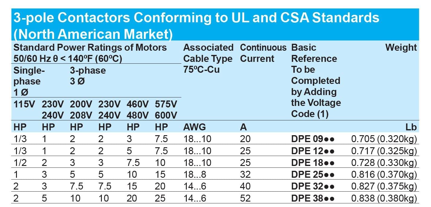
Motor Power Ratings (North American Market):
.jpg)
This table details standard power ratings for motors (50/60 Hz, θ < 140°F (60°C)) for single-phase and three-phase applications, associated cable types, continuous current, and reference model numbers for 3-pole contactors conforming to UL and CSA standards.

This table provides guidance on selecting the appropriate contactor based on motor power ratings for single-phase and three-phase systems, along with coil voltage codes for different applications (e.g., BL for 24VDC, U7 for 240VAC, G7 for 120VAC, B7 for 24VAC).
5. Setup & Installation
Proper installation is crucial for the safe and reliable operation of the contactor. Ensure all power is disconnected before beginning installation.
Mounting:
The DPE09G7 contactor can be mounted on a DIN-rail or directly fixed with screws.
- DIN-Rail Mounting: Snap the contactor onto a standard 35mm DIN-rail. Ensure it is securely latched.
- Screw Fixing: Use appropriate screws to fix the contactor to a panel through the designated mounting holes.
Wiring:
Refer to the wiring diagram provided with the product and adhere to all local electrical codes. The contactor features screw clamp terminals for connections.
- Power Circuit: Connect the incoming power lines to terminals 1L1, 3L2, and 5L3. Connect the load (e.g., motor) to terminals 2T1, 4T2, and 6T3.
- Control Circuit: Connect the 120V AC control voltage to the coil terminals A1 and A2.
- Auxiliary Contacts: Utilize the built-in 1NO (Normally Open) and 1NC (Normally Closed) auxiliary contacts for control logic as required. The NO contact is typically labeled 13-14, and the NC contact is typically labeled 21-22 (though the product description only mentions 1NO+1NC, the image shows 13 NO and 14 NO, implying a single NO contact). Please verify specific terminal markings on your unit.
- Ensure all connections are tight and free from loose strands.
6. Operation
The DPE09G7 contactor operates by energizing its coil, which closes the main power contacts, allowing current to flow to the connected load. De-energizing the coil opens the main contacts, interrupting the power.
- When the 120V AC control voltage is applied to terminals A1 and A2, the coil energizes.
- Upon coil energization, the main power contacts (1L1-2T1, 3L2-4T2, 5L3-6T3) close, and the built-in NO auxiliary contact closes (e.g., 13-14), while the NC auxiliary contact opens.
- When the control voltage is removed from A1 and A2, the coil de-energizes, causing the main power contacts to open, and the auxiliary contacts to return to their normal state.
For motor control applications, the contactor is typically controlled by a start/stop push-button station or a control system, often in conjunction with an overload relay for motor protection.
7. Maintenance
The Easy TeSys DPE contactor is designed for long-term, reliable operation with minimal maintenance. However, periodic inspection is recommended.
- Visual Inspection: Regularly check for any signs of physical damage, discoloration due to overheating, or loose connections.
- Cleaning: Ensure the contactor is free from dust and debris. Use a dry, soft cloth or compressed air for cleaning. Do not use liquids.
- Terminal Tightness: Periodically verify that all screw clamp terminals are securely tightened.
- Contact Wear: While not typically user-serviceable, excessive arcing or frequent operation under heavy loads can lead to contact wear. If operational issues arise, consider professional inspection.
Note: Any maintenance requiring disassembly should only be performed by qualified personnel.
8. Troubleshooting
This section addresses common issues you might encounter with the DPE09G7 contactor.
| Problem | Possible Cause | Solution |
|---|---|---|
| Contactor does not energize when control voltage is applied. |
|
|
| Contactor energizes but main contacts do not close or chatter. |
|
|
| Contactor hums excessively. |
|
|
| Overheating or discoloration. |
|
|
If troubleshooting steps do not resolve the issue, contact Schneider Electric technical support or a qualified electrician.
9. Compatible Accessories
The Easy TeSys DPE contactor is compatible with various Schneider Electric accessories to enhance functionality and protection.
- DPEAN11 Contact Block: Auxiliary contact block for additional control contacts.
- LAD9R1 Reversing Kit: Used for creating reversing contactor assemblies.
- GV2AF3 Mounting Interconnection Block: For direct mounting of a manual motor starter.
- DPER10 Overload Relay: Essential for motor protection against overcurrents.
- GP2E10 Manual Motor Starter: Provides motor protection and manual control.

The DPEAN11 auxiliary contact block provides additional 1NO+1NC instantaneous auxiliary contacts for enhanced control circuit flexibility.

The DPER10 thermal overload relay is designed to protect motors from overcurrents and phase loss, integrating directly with the contactor.

The GP2E10 manual motor starter offers both motor protection and manual ON/OFF control, often used in conjunction with contactors.
10. Warranty & Support
Warranty: This Schneider Electric product comes with an 18-month manufacturer's warranty from the date of purchase. This warranty covers defects in materials and workmanship under normal use and service. It does not cover damage resulting from improper installation, misuse, unauthorized modification, or external causes.
Support: For technical assistance, product information, or warranty claims, please contact Schneider Electric customer support through their official website or authorized distributors. Ensure you have your product model number (DPE09G7) and purchase details available when seeking support.
Visit the official Schneider Electric website for the latest documentation and support resources: www.se.com