
1. Introduction
This manual provides detailed instructions for the installation, operation, and maintenance of your MokerLink WiFi Bridge CPE. Designed for reliable external wireless transmission, this device facilitates Point-to-Point (PtP) and Point-to-MultiPoint (PtMP) connections, offering a stable 2.4 GHz 300 Mbps link over distances up to 1 KM.

Figure 1.1: MokerLink WiFi Bridge CPE units.
The image displays two white MokerLink WiFi Bridge CPE units, showcasing their sleek, rectangular design. These units are designed for outdoor use to establish wireless network links.
Key Features:
- 2.4 GHz Bandwidth: Operates on the 2.4 GHz frequency band with an integrated 8dBi antenna.
- High Speed & Range: Achieves up to 300 Mbps throughput and supports wireless transmission up to 1 KM.
- PoE Powered: Powered by a 24V PoE adapter (included), simplifying installation.
- One-Key Bridge Function: Supports dial coupling for easy Master/Slave configuration.
- Dual Ethernet Ports: Includes one WAN port for PoE connection and one LAN port for device connectivity.
- LED Display: Provides comprehensive information including Host-Client mode, signal strength, and IP address.
- Watchdog Chip: Built-in hardware protection circuit for automatic restart and continuous operation.
- Durable Design: Professional outdoor shell design with IP65 dustproof and waterproof rating, and lightning protection.
- WEB GUI Management: Supports web-based graphical user interface for status monitoring and configuration.

Figure 1.2: Overview of MokerLink WiFi Bridge features and transmission capability.
This diagram highlights the key features of the MokerLink WiFi Bridge, including One Key Bridge, LED Display, Watchdog, IP65 Waterproof, 1KM Transmission, and PoE Power. It visually represents the 1KM, 300Mbps wireless link between two buildings using the CPE units.
2. Setup Guide
2.1 Package Contents
Before beginning installation, please verify that all components are present:
- 2 x MokerLink WiFi Bridge CPE Units
- 2 x 24V PoE Adapters
- Mounting Accessories (straps/screws, not explicitly listed but implied by mounting options)
2.2 Physical Overview
Each CPE unit features a DIP switch (H/C), an LED display, WAN and LAN Ethernet ports, and a Reset (RST) button. The PoE adapter has a POE port for connecting to the CPE's WAN port and a LAN port for connecting to your network device.

Figure 2.1: MokerLink CPE unit features and outdoor design.
This image provides a close-up of the CPE unit, highlighting its LED display, IP65 waterproof rating, lightning protection for dual ports, and the PoE power connection setup. It emphasizes the product's suitability for outdoor environments.
2.3 Initial Configuration (One-Key Bridge)
The MokerLink WiFi Bridge supports a simplified one-key bridging process:
- Set Master and Slave: On one CPE unit, set the DIP switch to 'H' (Host/Master). On the second CPE unit, set the DIP switch to 'C' (Client/Slave).
- Connect Power: Connect the POE port of the 24V PoE adapter to the WAN port of each CPE unit. Plug the PoE adapters into power outlets.
- Initiate Pairing: Place both CPE units near each other. Simultaneously press the Reset (RST) button on both the Master and Slave CPE units. Hold for approximately 2-3 seconds. The units will automatically attempt to pair.
- Verify Pairing: Successful pairing is indicated by a specific pattern on the LED display (e.g., 'P' followed by a number indicating signal strength).
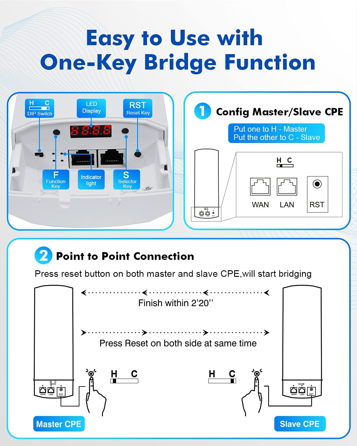
Figure 2.2: One-Key Bridge Function setup.
This image illustrates the simple setup process using the One-Key Bridge function. It shows how to configure one CPE as Master (H) and the other as Slave (C) using the DIP switch, and then how to establish a point-to-point connection by simultaneously pressing the reset buttons on both units.

Figure 2.3: Advanced One-Key Bridge and LED Display Bridge configuration.
This diagram provides more detailed steps for configuring the Master/Slave CPEs using the 'F' and 'S' buttons for the LED display bridge, and reiterates the point-to-point connection process by pressing the reset buttons.
2.4 Mounting the CPE Units
The CPE units are designed for flexible installation and can be mounted in various ways:
- Wall-Mountable: Securely attach the units to a flat wall surface using appropriate screws and anchors.
- Derrick-Mountable (Pole Mount): Use the provided straps or clamps to attach the units to a pole or mast. Ensure the units are oriented correctly for optimal signal alignment.
For best performance, ensure a clear line of sight between the Master and Slave units. Avoid obstructions like trees, buildings, or dense foliage.

Figure 2.4: Mounting options for MokerLink CPE.
This image illustrates the two primary mounting methods for the CPE units: derrick-mountable (pole mount) and wall-mountable. It also shows the adjustable angle for optimal signal alignment.
3. Operation
3.1 LED Display Information
The LED display on the CPE unit provides real-time operational status:
- H/C: Indicates Host (Master) or Client (Slave) mode.
- Number (e.g., 036): Represents the channel number.
- P: Appears after successful pairing, followed by a number indicating signal strength.
- A: Indicates the IP address.
- Port/WiFi/LED Power Supply Indicators: Show status of Ethernet ports, WiFi, and power.
Use the 'F' (Function) button to cycle through the displayed information and the 'S' (Selector) button to confirm settings.
3.2 WEB GUI Management
For advanced configuration and monitoring, the CPE units can be managed via a web-based graphical user interface (GUI). Refer to the product's full manual or manufacturer's website for default IP addresses and login credentials.
3.3 Watchdog Function
The MokerLink WiFi Bridge is equipped with an independent hardware protection circuit and a watchdog chip. In the event of a malfunction or abnormal operation, the device will automatically restart to maintain continuous wireless coverage, ensuring system stability and reliability.

Figure 3.1: Watchdog Function operation.
This image visually explains the Watchdog Function, showing how the system automatically re-connects and goes online after an offline state, ensuring continuous operation through self-recovery.
3.4 Adjustable Radio Transmit Power
The device can automatically regulate its power and transmission channel to reduce signal interference, particularly in environments with multiple CPEs or other wireless devices. This feature enhances the stability of the wireless link.

Figure 3.2: Adjustable Radio Transmit Power.
This diagram illustrates how adjustable radio transmit power helps reduce signal interference between multiple CPE units, showing a 'before' scenario with overlapping signals and an 'after' scenario with optimized, non-interfering signals.
3.5 Application Scenarios
The MokerLink WiFi Bridge supports various deployment modes:
- Point-to-Point (PtP) Bridge: Connects two distinct locations wirelessly (Master CPE in AP Mode, Slave CPE in Repeater Mode).
- Point-to-MultiPoint (PtMP): One Master CPE can connect to multiple Slave CPEs.
- Local Wireless Coverage (AP Mode): A single unit can be configured as an Access Point for local Wi-Fi access.

Figure 3.3: Point to Point Bridge and Local Wireless Coverage application diagrams.
This image presents two common application scenarios: the top diagram shows a Point-to-Point bridge setup connecting a camera and NVR system, while the bottom diagram illustrates local wireless coverage using the CPE as an Access Point for wireless cameras.
4. Maintenance
To ensure the longevity and optimal performance of your MokerLink WiFi Bridge CPE units, consider the following maintenance guidelines:
- Regular Cleaning: Periodically clean the exterior of the units to remove dust, dirt, and debris. Use a soft, dry cloth. Avoid abrasive cleaners or solvents.
- Inspect Cables: Check Ethernet cables and power connections for any signs of wear, damage, or corrosion. Replace damaged cables promptly.
- Environmental Protection: Although rated IP65 waterproof and dustproof, ensure the units are installed in locations that minimize direct exposure to extreme weather conditions where possible, and that drainage is adequate around the mounting area.
- Firmware Updates: Check the MokerLink official website periodically for any available firmware updates. Keeping the firmware updated can improve performance, stability, and security.
5. Troubleshooting
If you encounter issues with your MokerLink WiFi Bridge, consider the following basic troubleshooting steps:
- No Power: Ensure the PoE adapter is correctly connected to the CPE's WAN port and plugged into a working power outlet. Check the power indicator on the PoE adapter.
- No Link/Poor Signal:
- Verify clear line of sight between Master and Slave units.
- Check the LED display for signal strength (P indicator).
- Ensure both units are correctly configured as Master (H) and Slave (C).
- Re-attempt the one-key pairing process by simultaneously pressing the reset buttons.
- Network Connectivity Issues:
- Ensure the LAN port of the PoE adapter is connected to your network device (e.g., router, switch, PC).
- Verify IP address settings if you are using static IPs.
- Device Unresponsive: If a unit becomes unresponsive, the built-in watchdog function should automatically restart it. If not, try power cycling the unit by unplugging and re-plugging the PoE adapter.
- WEB GUI Access Issues: Ensure your computer's IP address is in the same subnet as the CPE's default IP (or configured IP). Try clearing your browser's cache.
For persistent issues or advanced troubleshooting, please refer to the detailed product manual available on the MokerLink website or contact MokerLink customer support.
6. Specifications
| Attribute | Value |
|---|---|
| Brand | MokerLink |
| Manufacturer Reference | WB300M |
| Wireless Type | 2.4 GHz Radio Frequency |
| Data Transfer Rate | 300 Megabits per Second |
| Data Link Protocol | Fast Ethernet |
| Hardware Interface | Ethernet |
| Voltage | 24 Volt |
| Color | White 1KM |
| Item Weight | 1.01 Kilograms |
| Compatible Devices | Desktop, Laptop, Tablet, Smartphone |
| Packaging Dimensions | 24.8 x 20.3 x 9.4 cm |
| ASIN | B099WJ6P57 |
7. Warranty and Support
7.1 Warranty Information
MokerLink products typically come with a manufacturer's warranty. For specific details regarding the warranty period, coverage, and terms for your WiFi Bridge CPE, please refer to the warranty card included with your product or visit the official MokerLink website. Retain your proof of purchase for warranty claims.
7.2 Customer Support
Should you require technical assistance, have questions about product functionality, or need to report an issue, please contact MokerLink customer support. Contact information can usually be found on the manufacturer's website or within the product packaging.


