LILYGO T-SIM7000G ESP32-WROVER-B Development Board User Manual
Model: T-SIM7000G
1. Introduction
The LILYGO T-SIM7000G ESP32-WROVER-B is a versatile development board integrating an ESP32 microcontroller with a SIM7000G module for cellular communication (2G/NB-IoT/LTE Cat-M1) and GPS functionality. It features a solar charging interface, a Nano SIM slot, and an 18650 battery holder, making it suitable for various IoT applications requiring low-power, remote connectivity, and location tracking.
2. Product Overview
This section provides a visual guide to the components of the LILYGO T-SIM7000G development board and its included accessories.
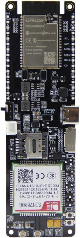
Figure 2.1: Front view of the LILYGO T-SIM7000G development board, showing the ESP32-WROVER-B module and SIM7000G cellular module.
Figure 2.2: Back view of the LILYGO T-SIM7000G development board, featuring the 18650 battery holder and pinout labels.
Figure 2.3: Labeled components of the LILYGO T-SIM7000G board, including USB Interface, Nano SIM Slot, Solar Charging Cable Interface, Power Switch, Reset Button, Battery Power Protection Reset, and SD Card slot. Identifiers visible on the SIM7000G module include P/N:S2-107Y8-Z1T69, SN:MP0620021100D54, IMEI:869951031158854, SW:1529B03SIM7000G.
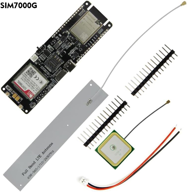
Figure 2.4: The LILYGO T-SIM7000G development board kit contents, typically including the main board, SIM antenna, GPS antenna, and pin headers.
Figure 2.5: Pinout diagram for the LILYGO T-SIM7000G ESP32, detailing GPIOs, power, and communication interfaces. Note: If GPIO12 is HIGH during external device startup, the program may enter an infinite reboot loop.
3. Setup
3.1. Antenna Connection
Connect the provided SIM antenna and GPS antenna to their respective U.FL connectors on the board. Ensure a secure connection. The SIM antenna is typically a thin wire, and the GPS antenna is a square ceramic patch.
Figure 3.1: SIM and GPS antennas connected to the LILYGO T-SIM7000G board.
3.2. Battery Installation
Insert an 18650 Lithium rechargeable cell into the battery holder on the back of the board. Observe correct polarity. The board supports solar charging via the dedicated interface, allowing for continuous operation in remote locations.
Figure 3.2: Example of connecting a solar panel to the LILYGO T-SIM7000G for battery charging.
3.3. SIM Card Insertion
Insert a Nano SIM card into the Nano SIM slot. Ensure the USIM card you use supports 2G (GSM) or NB-IoT access for cellular connectivity. The SIM7000G module does not support standard 4G networks (e.g., for smartphones), but it does support LTE Cat-M1, which is a narrowband IoT variant of LTE.
3.4. Driver Installation
Before connecting the board to your computer via USB, install the CH9102 driver. This driver is necessary for your computer to recognize the board and enable serial communication for programming and debugging. Drivers can typically be found on the LILYGO GitHub page or through a web search for "CH9102 driver".
3.5. Initial Power-Up
After connecting antennas, battery, and SIM card, connect the board to your computer using a USB cable. Use the power switch located on the side of the board to turn on the device. The board can then be programmed using environments such as Arduino IDE, PlatformIO, or MicroPython.
4. Operating Instructions
4.1. Programming and Development
The LILYGO T-SIM7000G is based on the ESP32-WROVER-B module, allowing development with various platforms. Refer to the official LILYGO GitHub repository for examples and libraries: github.com/Xinyuan-LilyGO/LilyGO-T-SIM7000G.
Arduino IDE: Install the ESP32 board definitions and necessary libraries.
PlatformIO: Configure your project for the ESP32 platform.
MicroPython: Flash MicroPython firmware and use a serial terminal for programming.
4.2. Cellular Communication (SIM7000G)
The integrated SIM7000G module supports 2G (GSM), NB-IoT, and LTE Cat-M1. It is important to note that the SIM7000G does not support standard 4G/LTE (e.g., for smartphones). Ensure your SIM card and service plan are compatible with these specific IoT network types.
AT Commands: The SIM7000G module is controlled via AT commands. Libraries like TinyGSM can simplify interaction.
Network Access: Configure the Access Point Name (APN) according to your cellular provider's requirements.
4.3. GPS Functionality
The SIM7000G module includes GPS capabilities. Ensure the GPS antenna is connected and has a clear view of the sky for optimal signal reception and accuracy. GPS data can be accessed via AT commands.
4.4. Power Management
The board features an 18650 battery holder and a solar charging input. The ESP32 supports deep sleep modes for power optimization. Careful consideration of power consumption in deep sleep is advised, as some components may still draw current, potentially leading to higher than expected battery drain.
5. Maintenance
Battery Care: Use high-quality 18650 batteries. Avoid over-discharging or over-charging. If using solar charging, ensure the solar panel is appropriately sized for the battery and charging circuit to prevent damage.
Firmware Updates: The SIM7000G module supports Firmware Over-The-Air (FOTA) updates. Refer to the module's documentation for details on this process. Regularly check for ESP32 firmware updates for improved performance and security.
Environmental Conditions: Operate the board within its specified temperature and humidity ranges. Avoid exposure to moisture, dust, and extreme temperatures to ensure longevity.
Cleaning: Use a soft, dry, anti-static cloth to clean the board. Avoid liquids or abrasive cleaners, which can damage components.
6. Troubleshooting
6.1. Connectivity Issues
No Cellular Connection:
Ensure the SIM antenna is securely connected.
Verify that your Nano SIM card is active and supports 2G (GSM), NB-IoT, or LTE Cat-M1. Standard 4G/5G SIMs may not work with the SIM7000G module.
Check the Access Point Name (APN) settings in your code; these must match your cellular provider's requirements.
Confirm that the cellular network in your area supports the SIM7000G's frequency bands.
No GPS Fix:
Ensure the GPS antenna is securely connected and has an unobstructed view of the sky.
GPS accuracy can vary based on environmental factors. Expect typical accuracy in the range of several meters, not sub-meter precision.
USB Connection Not Recognized:
Install the CH9102 driver for your operating system.
Try a different USB cable or port on your computer.
6.2. Programming and Software Issues
Upload Errors:
Reduce the upload speed in your IDE settings (e.g., Arduino IDE Tools -> Upload speed) if you encounter frequent upload failures.
Ensure the correct board and COM port are selected in your development environment.
Infinite Reboot Loop:
Check if GPIO12 is inadvertently pulled HIGH during startup, especially if external devices are connected to it. This can prevent the ESP32 from booting correctly.
Complex Functionality (e.g., SMS Receive, MQTT over TLS):
Some advanced features may require more in-depth understanding of AT commands and module interaction. Refer to the SIM7000G datasheet and community forums for detailed examples and support.
6.3. Power Management Issues
High Battery Drain in Deep Sleep:
While the ESP32 supports deep sleep, ensure all peripheral components (SIM7000G, sensors, etc.) are properly powered down or put into low-power modes to minimize current draw.
Consider adding external power monitoring or cutoff circuits for critical low-voltage protection, as the board may not have an integrated controller to force shutdown at low battery levels.
7. Specifications
Key technical specifications for the LILYGO T-SIM7000G development board:
Feature
Detail
MCU
ESP32-WROVER-B (Dual-core, 240MHz)
Flash Memory
16 MB
PSRAM
8 MB
Cellular Module
SIM7000G (Global)
Cellular Connectivity
2G (GSM), NB-IoT, LTE Cat-M1
SIM Card Type
Nano SIM
GPS/GNSS
Beidou, GPS, GLONASS
Wireless Connectivity
Wi-Fi (802.11 b/g/n), Bluetooth (v4.2 BR/EDR and BLE)
Peripheral Interfaces
I2C, SPI, UART, SDIO, I2S, CAN, GPIO
USB Interface
1x USB (for power, programming, serial communication)
Operating System
FreeRTOS (ESP32)
Power Supply
3.0V ~ 4.3V (via 18650 battery or USB)
Charging
Integrated 18650 battery charger, Solar charging input
Dimensions (L x W x H)
4.37" x 1.46" x 0.79" (approx. 111mm x 37mm x 20mm)
Included Accessories
USB cable, SIM antenna, GPS antenna, Pin headers
Figure 7.1: Detailed specifications table for the SIM7000G module, including frequency bands, power consumption, data transfer rates, GNSS support, and protocols.
Figure 7.2: Comparison table highlighting differences between the T-SIM7000G (Global) and T-SIM7000A (America) versions, primarily in cellular module and regional support.
8. Warranty and Support
8.1. Warranty Information
Specific warranty details for this product are not provided in the available information. Please refer to the retailer or manufacturer's official website for current warranty policies.
8.2. Technical Support
For technical assistance, detailed documentation, and code examples, please visit the official LILYGO GitHub repository: