1. Introduction
This manual provides comprehensive instructions for the installation, operation, and maintenance of the Maxsun Challenger A10 Quad-Core Super V2.0 Motherboard. Please read this manual thoroughly before proceeding with installation to ensure proper setup and optimal performance. This motherboard is designed for personal computer systems, offering robust performance with its integrated A10-RX425BB Quad Core CPU and DDR3 memory support.
2. Product Overview
The Maxsun Challenger A10 Quad-Core Super V2.0 is an m-ATX form factor motherboard (220 x 170mm) featuring an integrated A10-RX425BB Quad Core CPU. This combination provides a compact yet powerful solution for various computing needs. Key features include:
- Integrated A10-RX425BB Quad Core CPU with 3.4 / 2.5GHz frequency.
- GPU frequency of 654/576 MHz.
- 4 MB secondary cache.
- Low power consumption of 35W.
- Dual channel DDR3 memory slots.
- Three SATA 3.0 ports for storage connectivity.
- Multiple USB 2.0 ports and a Gigabit network card.
- HDMI and VGA display interfaces.
- 5.1 channel audio interface.
- PCI Express graphics card interface.

Figure 2.1: Maxsun Challenger A10 Motherboard with key components labeled, including A10-RX425BB CPU, DDR3 slots, SATA 3.0 ports, USB 2.0 ports, PS/2, COM, VGA, HDMI, and PCIe slots.

Figure 2.2: Overall view of the Maxsun Challenger A10 Motherboard, showcasing the integrated CPU heatsink and general layout.
3. Specifications
| Feature | Detail |
|---|---|
| Motherboard Type | m-ATX (220 x 170mm) |
| CPU | Integrated A10-RX425BB Quad Core |
| CPU Frequency | 3.4 / 2.5GHz |
| GPU Frequency | 654 / 576 MHz |
| Secondary Cache | 4 MB |
| Power Consumption | 35W |
| RAM Memory Technology | DDR3 |
| Memory Slots Available | 2 (Dual Channel) |
| SATA Ports | 3 x SATA 3.0 |
| USB Ports | Multiple USB 2.0 |
| Network Interface | Gigabit Network Card |
| Video Interfaces | HDMI, VGA |
| Audio Interface | 5.1 Channel Audio |
| Graphics Card Interface | PCI Express |
| Compatible Devices | Personal Computer |

Figure 3.1: Detailed view of the dual DDR3 memory slots and the chipset area on the motherboard.
4. Setup and Installation
Before beginning installation, ensure your system is powered off and disconnected from the power source. Handle the motherboard by its edges to avoid static discharge.
4.1. Motherboard Mounting
- Align the motherboard with the standoffs in your computer case.
- Secure the motherboard using appropriate screws, ensuring it is firmly seated but not overtightened.
4.2. RAM Installation
- Locate the two DDR3 memory slots.
- Open the clips at both ends of the memory slot.
- Align the notch on the DDR3 memory module with the key in the slot.
- Press down firmly on both ends of the memory module until the clips snap into place.
4.3. Storage Device Connection
- Connect your SATA storage devices (HDDs/SSDs) to the SATA 3.0 ports on the motherboard using SATA data cables.
- Ensure power cables from your power supply are connected to the storage devices.
4.4. Power Supply Connection
- Connect the 24-pin ATX power connector from your power supply to the main power socket on the motherboard.
- Connect the 4-pin CPU power connector (if present) to the corresponding socket near the CPU area.
4.5. Front Panel Connections
Connect the front panel cables (Power SW, Reset SW, HDD LED, Power LED, USB, Audio) from your case to the corresponding headers on the motherboard. Refer to your case manual for specific pin assignments if needed.
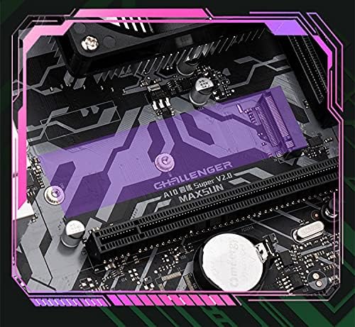
Figure 4.1: View of the M.2 slot, which can be used for high-speed storage devices.
5. Operating Instructions
5.1. Initial Boot-up
- After all components are installed and connected, connect your monitor, keyboard, and mouse.
- Connect the power cord to your power supply and turn on the power switch.
- Press the power button on your computer case. The system should power on and display the BIOS/UEFI splash screen.
5.2. BIOS/UEFI Setup
During the initial boot-up, press the designated key (commonly DEL, F2, or F10) to enter the BIOS/UEFI setup utility. Here you can configure boot order, system time, and other hardware settings.
5.3. Operating System Installation
Once BIOS/UEFI settings are configured, you can proceed with installing your preferred operating system from a bootable USB drive or DVD. Follow the on-screen instructions provided by your operating system installer.
6. Maintenance
6.1. Cleaning
Regularly clean dust from the motherboard and components using compressed air. Ensure the system is powered off and unplugged before cleaning. Pay particular attention to the CPU heatsink and fan to maintain optimal cooling performance.
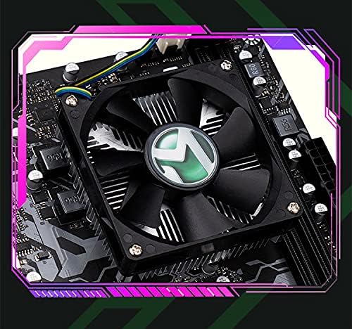
Figure 6.1: Close-up view of the integrated CPU heatsink and fan, crucial for thermal management.
6.2. Driver Updates
Periodically check the manufacturer's website for updated drivers for the motherboard chipset, integrated graphics, and other components. Keeping drivers up-to-date can improve system stability and performance.
7. Troubleshooting
7.1. No Power / No Boot
- Ensure all power cables (24-pin ATX, 4-pin CPU) are securely connected to the motherboard and power supply.
- Verify the power supply switch is in the 'ON' position.
- Check front panel power button connection to the motherboard.
- Test with a different power supply if possible.
7.2. No Display Output
- Ensure the monitor is connected to the correct video output port (HDMI or VGA) on the motherboard.
- Verify the monitor is powered on and set to the correct input source.
- Reseat RAM modules to ensure they are properly installed.
7.3. System Instability / Crashes
- Check for proper seating of all components (RAM, storage drives).
- Ensure adequate cooling; clean the CPU heatsink and case fans.
- Update motherboard drivers and BIOS/UEFI firmware.
8. Warranty and Support
For warranty information and technical support, please refer to the documentation provided with your purchase or contact the seller/manufacturer directly. Keep your proof of purchase for warranty claims.
Brand: RKRJJJ