1. Product Overview
The ele ELEOPTION 530SE Primary Control Box is a critical component for oil burner systems, designed to manage and monitor the combustion process. This unit integrates flame detection, ignitor management, and fuel valve operation to ensure safe and efficient burner performance. It serves as a direct replacement for primary control units in various heating systems.
The 530SE is compatible with a wide range of oil burners, including Riello 40G models and other systems within the G3, G5, G10, G20, G5LC, G10LC, G20LC, and G20S series.

Image 1.1: Top view of the 530SE Primary Control Box, showing warning labels and the red lockout indicator.
2. Safety Information
WARNING: HIGH VOLTAGE. This device operates with high voltage (8 KV - 16 mA). Improper installation or handling can result in serious injury or death. Always disconnect power before servicing or installing this unit.
- Installation and servicing must be performed by a qualified and licensed technician.
- Ensure all local and national electrical codes are followed.
- Use COPPER CONDUCTORS ONLY for wiring connections.
- Do not bypass any safety features or interlocks.
- The unit features microprocessor-driven safeguards that automatically initiate lockouts after ignition failures or flame loss. Do not attempt to override these safety mechanisms.
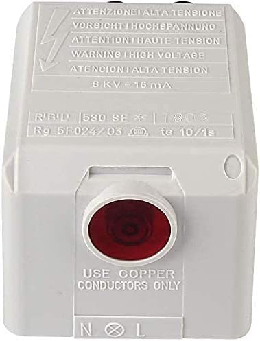
Image 2.1: Close-up of the 530SE Control Box highlighting the high voltage warning label.
3. Key Features and Functions
The 530SE Primary Control Box is engineered with several key features to ensure reliable and safe oil burner operation:
- Complete Combustion Control System: Integrates flame detection, ignitor management, and fuel valve operation. A high-sensitivity electric eye continuously monitors flame presence, triggering instant shutdown during failures to prevent hazardous fuel buildup.
- Universal Oil Burner Compatibility: Designed as a direct replacement for primary control units across diverse heating systems, including residential and commercial oil burners.
- Advanced Safety Protections: Microprocessor-driven safeguards automatically initiate lockouts after ignition failures or flame loss. Diagnostic LEDs provide clear fault codes for efficient troubleshooting.
- Quick-Install Design: Features pre-calibrated flame sensor and standardized wiring terminals for straightforward replacement.
- Industrial-Grade Resilience: Built to endure extreme boiler-room conditions with heat-shielded circuitry, vibration-resistant connectors, and moisture-proof housing.
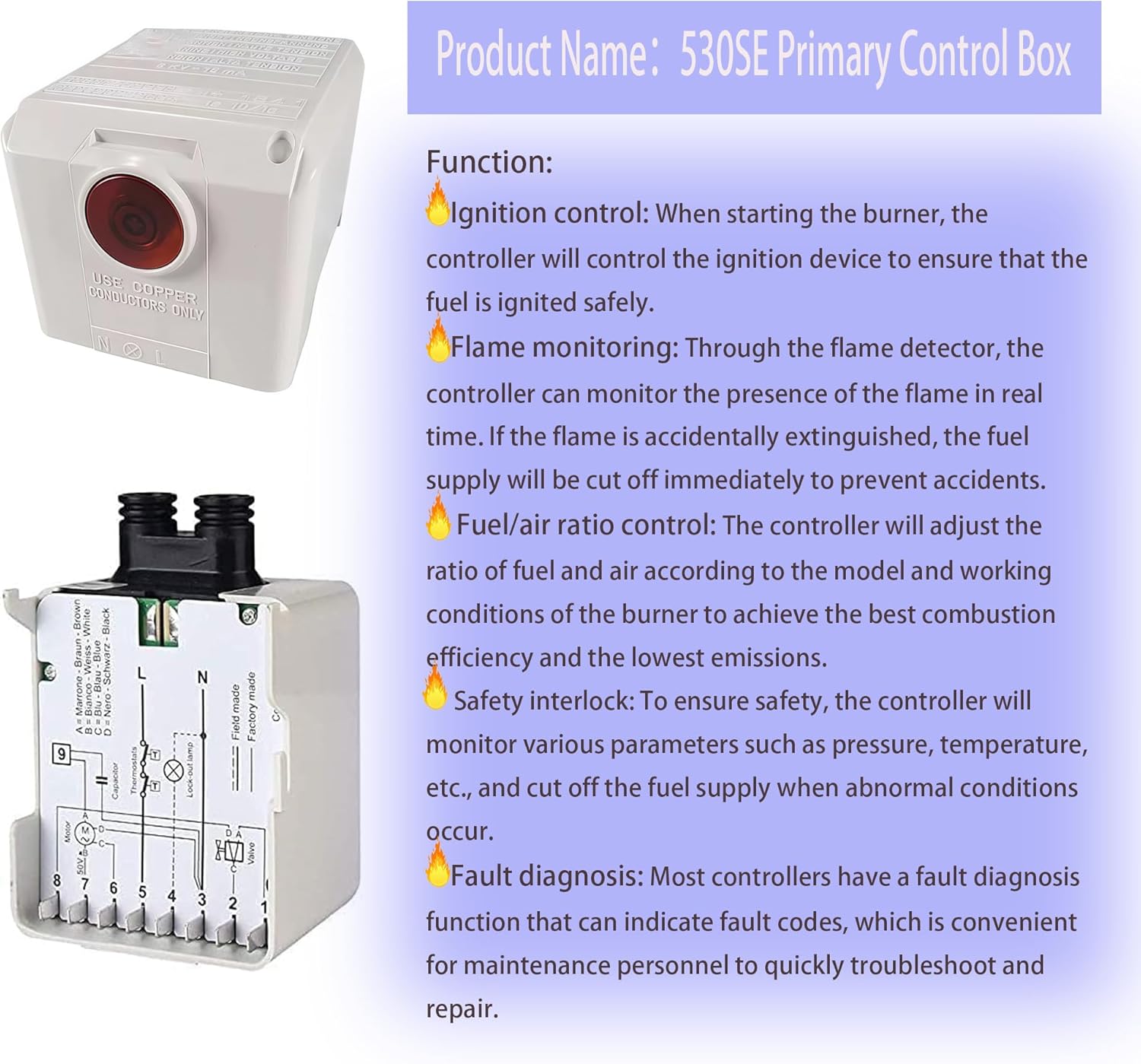
Image 3.1: The 530SE Control Box with an overlay describing its primary functions: Ignition control, Flame monitoring, Fuel/air ratio control, Safety interlock, and Fault diagnosis.
4. Setup and Installation
Installation of the 530SE Primary Control Box should only be performed by a qualified technician. Refer to the wiring diagram provided with the unit and the specific oil burner manufacturer's instructions.
4.1 Wiring Connections
Ensure all power to the oil burner system is disconnected before beginning installation. Connect the control box according to the circuit diagram, paying close attention to the line (L), neutral (N), and ground connections, as well as connections for the motor, valve, thermostat, and photoelectric eye.

Image 4.1: Bottom view of the 530SE Control Box, showing the integrated circuit diagram, photoelectric eye installation position, and high voltage output ports.
4.2 Photoelectric Eye Installation
The photoelectric eye (flame sensor) must be correctly positioned to accurately detect the presence of flame in the combustion chamber. Refer to the burner manufacturer's guidelines for optimal placement. The control box provides a dedicated connection point for this sensor.
4.3 High Voltage Output
The high voltage output ports are for connecting to the ignitor electrodes. Ensure these connections are secure and properly insulated to prevent arcing and maintain safety.

Image 4.2: Detailed view of the circuit diagram for the 530SE Control Box, illustrating connections for L, N, motor, valve, thermostat, and lockout lamp.
5. Operating Instructions
Once installed and wired correctly, the 530SE Control Box operates automatically to manage the oil burner's ignition and combustion cycle.
- Ignition Sequence: Upon a call for heat, the control box initiates the ignitor and opens the fuel valve. The photoelectric eye monitors for flame establishment.
- Flame Monitoring: After successful ignition, the photoelectric eye continuously monitors the flame. If the flame is lost during operation, the control box will immediately shut off the fuel supply to prevent unburnt fuel accumulation.
- Lockout: If ignition fails within the specified safety time, or if the flame is lost and cannot be re-established, the control box will enter a lockout state. The red indicator light on the unit will illuminate, and the burner will cease operation.
5.1 Resetting from Lockout
To reset the control box from a lockout state, press the red reset button on the front of the unit. Before resetting, it is crucial to identify and rectify the cause of the lockout. Repeated lockouts indicate a persistent issue that requires professional diagnosis.
6. Maintenance
The 530SE Primary Control Box is designed for durability and minimal maintenance. However, regular inspection of the overall oil burner system is recommended to ensure optimal performance and longevity of all components, including the control box.
- Ensure the control box and its connections are free from dust, dirt, and moisture.
- Periodically check all wiring connections for tightness and signs of wear.
- Ensure the photoelectric eye lens is clean and unobstructed for accurate flame detection.
- Any internal servicing or repair should only be conducted by a qualified technician.
7. Troubleshooting
The 530SE Control Box provides diagnostic feedback through its lockout indicator. If the burner fails to operate or enters a lockout state, consider the following:
- No Ignition / Lockout:
- Check power supply to the burner system.
- Verify fuel supply is open and adequate.
- Inspect ignitor electrodes for proper gap and cleanliness.
- Clean or replace the photoelectric eye if it is dirty or faulty.
- Check for air in the fuel line.
- Burner Starts, then Locks Out:
- Indicates flame loss during operation. Check photoelectric eye for proper function and cleanliness.
- Ensure stable fuel and air mixture.
- Inspect nozzle and combustion chamber for issues.
- No Power to Control Box:
- Check circuit breaker or fuse.
- Verify thermostat is calling for heat.
- Inspect wiring connections for loose or damaged wires.
For complex issues or persistent problems, contact a certified HVAC technician. Do not attempt repairs beyond your qualifications.
8. Specifications
| Specification | Detail |
|---|---|
| Model | 530SE |
| Compatibility | Riello 40G Oil Burner Controller, G3 / G5 / G10 / G20 / G5LC / G10LC / G20LC / G20S series |
| Voltage Output | 8 KV - 16 mA (High Voltage) |
| Item Weight | 13.4 ounces |
| Package Dimensions | 5.31 x 5.31 x 3.11 inches |
| Batteries Required | No |
| ASIN | B099DFGKQZ |
| Date First Available | January 18, 2024 |
9. Warranty and Support
For warranty information and technical support regarding your ele ELEOPTION 530SE Primary Control Box, please refer to the documentation provided at the time of purchase or contact the seller directly. Specific warranty terms may vary.
For further assistance, you may visit the ele ELEOPTION Store online or contact their customer service department.