1. Introduction
This manual provides essential information for the safe and efficient operation of the EPEVER Tracer 10420AN Series MPPT Solar Charge Controller. This device is designed to manage the power flow from solar panels to batteries, ensuring optimal charging and protecting the battery from overcharge and over-discharge. It is compatible with 12V, 24V, 36V, and 48V battery systems and supports various battery types including lead-acid (sealed, gel, flooded) and lithium batteries (LiFePO4, Li(NiCoMn)O2).
Key features include a 200V PV input, 100A charging current, dual RS485 ports for parallel operation (up to 8 units), and support for remote monitoring via MT50 meter, PC software, or mobile apps.
2. Safety Information
- Always connect the battery first, then the solar panel, and finally the load. Disconnect in the reverse order.
- Ensure all wiring is correctly polarized and securely connected to prevent damage to the controller or battery.
- Install the controller in a well-ventilated area, away from flammable materials and direct sunlight.
- Do not disassemble or attempt to repair the controller yourself. Refer to qualified personnel for service.
- Use appropriate circuit breakers or fuses for the battery and PV input circuits.
- The controller is designed for negative ground systems.
3. Package Contents
Verify that all items listed below are included in your package:
- EPEVER Tracer 10420AN MPPT Solar Charge Controller
- MT50 Remote Meter
- PAL-ADP-50AN Parallel Adapter
- Temperature Sensor Cable
- USB Communication Cable (CC-USB-RS485-150U)
- RJ45 Ethernet Cable (for MT50 and parallel adapter)

This image displays the main components included in the product package: the large MPPT solar charge controller, the smaller MT50 remote meter, the PAL-ADP-50AN parallel adapter, a USB communication cable, and an RJ45 Ethernet cable.
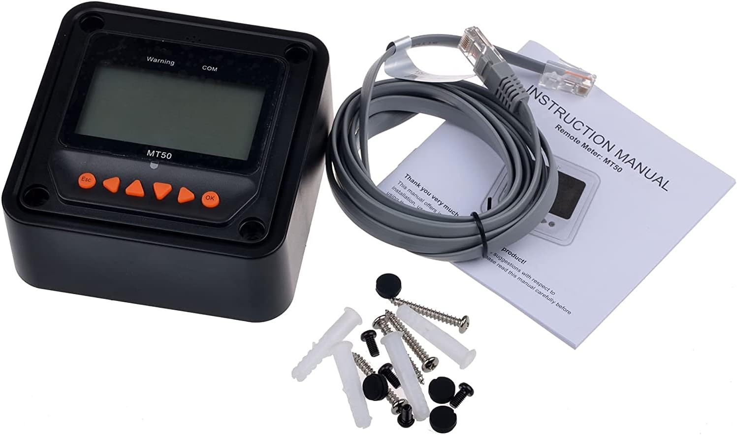
This image shows the MT50 remote meter, its instruction manual, an RJ45 communication cable, and mounting screws with wall anchors.
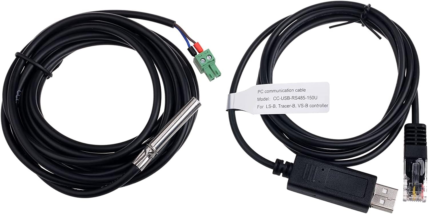
This image displays two important cables: a black temperature sensor cable with a metal probe and a green connector, and a black USB communication cable (Model: CC-USB-RS485-150U) with a USB-A connector on one end and an RJ45 connector on the other.

This image shows the black PAL-ADP-50AN parallel adapter, which has multiple RS485 ports, along with a grey RJ45 Ethernet cable used for communication between controllers.
4. Product Overview
The EPEVER Tracer 10420AN is an advanced MPPT solar charge controller designed for high-efficiency solar power systems. It features a robust design with multiple connection points for PV input, battery, and load, along with communication ports for external devices.

This image provides a top-down view of the solar charge controller with its protective terminal covers lifted, revealing the various connection points for solar panels, battery, and load. The display screen and control buttons are also visible.
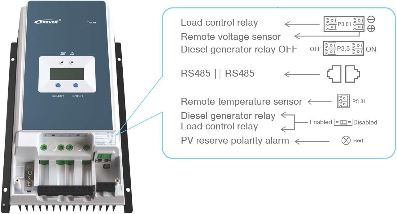
This image highlights the various ports and indicators on the side of the controller, including connections for load control relay, remote voltage sensor, diesel generator relay, RS485 communication ports, remote temperature sensor, and a PV reverse polarity alarm indicator.

This image shows an angled perspective of the PAL-ADP-50AN parallel adapter, emphasizing its multiple RS485 ports for connecting and synchronizing several solar charge controllers.
5. Setup and Installation
Proper installation is crucial for the performance and longevity of your solar charge controller. Follow these steps carefully:
5.1 Mounting the Controller
- Choose a dry, well-ventilated location, protected from direct sunlight, high temperatures, and moisture.
- Ensure there is sufficient clearance around the controller for heat dissipation.
- Mount the controller vertically on a non-flammable surface using appropriate screws.
5.2 Wiring Connections
Follow the wiring diagram below for correct connections. Always connect the battery first, then the solar array, and finally the load. Ensure all connections are tight and secure.

This diagram illustrates the typical wiring setup for the EPEVER Tracer AN series solar charge controller. It shows connections from the solar panels to the controller, from the controller to the battery bank, and from the battery bank to a power inverter and then to AC loads. The diagram emphasizes a common negative design and includes grounding points.
- Battery Connection: Connect the battery cables to the battery terminals on the controller. Ensure correct polarity (+ to + and - to -). The controller will automatically detect the battery voltage.
- Solar Panel Connection: Connect the solar panel cables to the PV input terminals on the controller. Observe correct polarity. Ensure the open-circuit voltage of your solar array does not exceed the controller's maximum PV input voltage (200V).
- Load Connection (Optional): If using the load output, connect your DC loads to the load terminals. Note that the Tracer 10420AN series does not have a direct load output; this connection is typically for external relays or inverters.
- Remote Temperature Sensor: Connect the included temperature sensor to the designated port on the controller. This allows for accurate battery temperature compensation during charging.
- Communication Ports (RS485): Use the RS485 ports for connecting the MT50 remote meter, PC communication cable, or the PAL-ADP-50AN parallel adapter for multi-unit systems.
6. Operating Instructions
Once installed, the controller will begin operating automatically. You can monitor and configure settings using the built-in display or the MT50 remote meter.
6.1 Display and Buttons
The controller features an LCD display and two buttons: "SELECT" and "ENTER".
- SELECT: Used to navigate through different display screens or menu options.
- ENTER: Used to confirm a selection or enter a setting mode.
6.2 MT50 Remote Meter Operation
The MT50 remote meter provides a more convenient way to monitor system status and adjust parameters.

This image shows the illuminated display of the MT50 remote meter, indicating various system parameters such as solar panel voltage (35.5V), current (1.6A), battery voltage (14.7V), battery current (3.9A), and load voltage (0.0V) and current (0.0A). Icons for solar, battery, and load are also visible.
- Connect the MT50 to the controller's RS485 port using the provided RJ45 cable.
- The MT50 display will show real-time data such as PV voltage, charging current, battery voltage, and load status.
- Use the navigation buttons (Esc, Up, Down, Right, Left, OK) to browse menus and modify settings like battery type, charging parameters, and load control modes.
6.3 Battery Type Configuration
The controller supports four charging options: Sealed, Gel, Flooded, and User-defined. It is critical to select the correct battery type for optimal charging and battery longevity.
- Access the battery settings menu via the controller's display or MT50 meter.
- Select the battery type that matches your installed battery.
- For User-defined, you can manually set charging voltages (e.g., boost, float, low voltage disconnect).
6.4 Parallel Operation (with PAL-ADP-50AN)
The PAL-ADP-50AN Parallel Adapter allows up to 6 controllers to operate in parallel, sharing data and synchronizing parameters for larger systems.
- Connect each controller to the PAL-ADP-50AN adapter using RJ45 cables.
- The adapter ensures consistent parameters across all connected controllers.
7. Maintenance
Regular maintenance ensures the long-term performance and safety of your solar charge controller.
- Check Connections: Periodically inspect all wiring connections for tightness and corrosion. Loose connections can cause overheating and damage.
- Clean the Controller: Keep the controller clean and free of dust and debris. Ensure the heat sink fins are not obstructed to allow for proper cooling. Use a dry cloth for cleaning.
- Inspect Wiring: Check for any signs of wear, fraying, or damage to the cables. Replace damaged cables immediately.
- Battery Inspection: Regularly check your battery terminals for corrosion and clean them if necessary. Ensure battery ventilation is adequate.
- System Performance: Monitor the system's performance regularly using the display or MT50 meter to ensure it is operating within expected parameters.
8. Troubleshooting
This section addresses common issues you might encounter with your solar charge controller.
| Problem | Possible Cause | Solution |
|---|---|---|
| Controller display is off. | No battery connected or battery voltage is too low. | Check battery connections. Ensure battery voltage is above the minimum operating voltage (typically 9V for 12V systems). |
| No charging current from PV. | PV input reversed, PV voltage too low, or solar panels are shaded/damaged. | Check PV polarity. Ensure PV voltage is higher than battery voltage. Inspect solar panels for shading or damage. |
| Battery not fully charged. | Incorrect battery type setting, insufficient PV power, or high battery internal resistance. | Verify battery type setting. Increase PV array size if needed. Check battery health. |
| Over-temperature alarm. | Poor ventilation, high ambient temperature, or excessive load. | Improve ventilation around the controller. Reduce load if possible. Ensure heat sink is clean. |
| Communication error with MT50/PC. | Loose cable connection, incorrect port, or software issue. | Check RJ45 cable connections. Ensure correct RS485 port is used. Restart software/device. |
9. Specifications
| Parameter | Value |
|---|---|
| System Nominal Voltage | 12V/24V/36V/48V Auto Recognition |
| Battery Input Voltage Range | 9V ~ 64V |
| Max. PV Open Circuit Voltage | 200V (at 25°C), 190V (at -25°C) |
| Max. PV Input Power | 1250W/12V, 2500W/24V, 3750W/36V, 5000W/48V |
| Rated Charge Current | 100A |
| MPPT Tracking Efficiency | ≥99.5% |
| Conversion Efficiency | Max. 98% |
| Grounding | Negative Ground |
| Communication | Dual RS485 ports (RJ45) |
| Operating Temperature Range | -25°C to +50°C |
10. Warranty and Support
SolarEpic products are designed for reliability and performance. For warranty information and technical support, please refer to the official SolarEpic website or contact their customer service directly.
- Warranty: Please refer to the warranty card included with your product or visit the SolarEpic official website for detailed warranty terms and conditions.
- Technical Support: For technical assistance, troubleshooting, or service requests, please contact SolarEpic customer support. Have your product model and serial number ready.
- Online Resources: Additional resources, FAQs, and software updates may be available on the SolarEpic website.
For more information, visit the SolarEpic Store on Amazon.