JUWEIAT DL24P
JUWEIAT 180W Electronic Load Tester User Manual
Model: DL24P
Brand: JUWEIAT
1. Introduction
The JUWEIAT 180W Electronic Load Tester (Model DL24P) is a versatile instrument designed for comprehensive testing and aging of various power sources and batteries. It provides precise measurements of voltage, current, power, capacity, energy, temperature, and discharge time. With its 2.4-inch high-definition color screen and support for four-wire measurement, it offers accurate and detailed analysis for professionals and enthusiasts alike.
This manual provides detailed instructions for setting up, operating, and maintaining your electronic load tester to ensure optimal performance and longevity.

Figure 1.1: JUWEIAT 180W Electronic Load Tester with included power adapter and cables.
2. Key Features
- Wide Compatibility: Capable of testing USB chargers, power banks, various battery types (including lithium), and power adapters for voltage, current, power, capacity, temperature, and discharge resistance.
- Multiple APP Support: Features four online APPs (Android, Apple, PC) with Bluetooth wireless and wired connection options for data monitoring and control.
- Four Discharge Modes: Supports Constant Current (CC), Constant Power (CP), Constant Resistance (CR), and Constant Voltage (CV) discharge modes.
- Four-Wire System Advantage: Provides more accurate voltage measurements by eliminating wire voltage drop, especially crucial for battery testing. Supports 2-wire system as well.
- High-Definition Display: Equipped with a 2.4-inch wide color screen for clear display of multiple parameters.
- Intelligent Protection: Includes built-in over-current, over-temperature, and over-power safety protection functions.
- Smart Temperature Control: Features an intelligent temperature control fan design for efficient heat dissipation during high-power discharge tests.
3. Product Components and Interface
Familiarize yourself with the various parts and connection points of the DL24P Electronic Load Tester.

Figure 3.1: Overview of the DL24P Electronic Load Tester's interface and components, including input ports, buttons, and display.
3.1 Main Components
- Main Circuit Board: Houses the control logic and measurement circuitry.
- Cooling Fan: Intelligent temperature-controlled fan for heat dissipation. Features a multi-color LED ring.
- 2.4-inch Color Display: Shows real-time measurement data and settings.
- Control Buttons: Four buttons for navigation and setting adjustments (Power, Setup, +, -).
- Input Terminals: Screw terminals for connecting the load (A+ and V+ for 4-wire, A- and V- for 4-wire, or A+ and A- for 2-wire).
- Input Ports: DC 5.5 input, Mini USB input, Micro USB input, Type-C input detection ports.
- External NTC Temperature Probe Port: For connecting an external temperature sensor.
- Bluetooth Module: For wireless connectivity to APP (built-in in upgraded versions).

Figure 3.2: Product update showing the built-in Bluetooth module for enhanced connectivity.
4. Setup and Initial Connection
Before operating the DL24P, ensure proper setup and connection to the power source or battery you intend to test.
4.1 Powering the Device
- Connect the provided power adapter to the DC 5.5 input port on the electronic load tester.
- Plug the power adapter into a suitable wall outlet. The device display should illuminate.
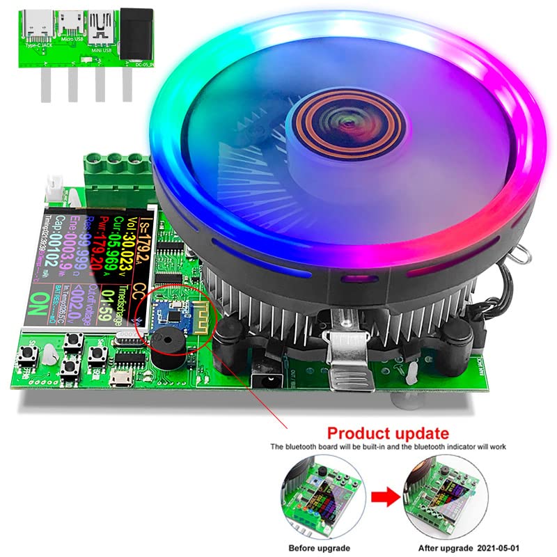
Figure 4.1: Connecting the power adapter to the DL24P.
4.2 Connecting the Load (Battery/Power Supply)
The DL24P supports both 2-wire and 4-wire connections. For optimal accuracy, especially with battery testing, the 4-wire method is recommended.
4.2.1 4-Wire Connection (Recommended for Batteries)
- Connect the main load wires (thicker wires) from the positive terminal of your battery/power supply to the A+ terminal and from the negative terminal to the A- terminal on the tester.
- Connect the voltage sensing wires (thinner wires) from the positive terminal of your battery/power supply to the V+ terminal and from the negative terminal to the V- terminal on the tester.
- Ensure all connections are secure to prevent sparking or inaccurate readings.
4.2.2 2-Wire Connection
- Connect the positive wire from your battery/power supply to the A+ terminal.
- Connect the negative wire from your battery/power supply to the A- terminal.
- Note: In 2-wire mode, the voltage measurement may be slightly affected by the voltage drop across the load wires.
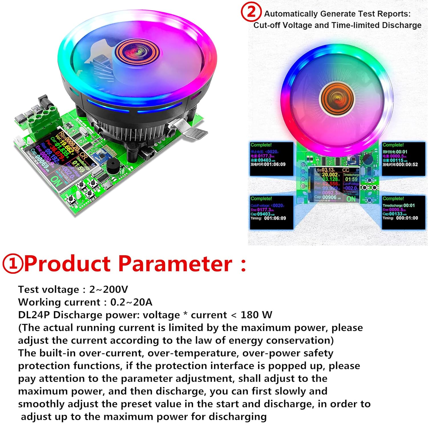
Figure 4.2: Illustration of battery connection for internal resistance detection, demonstrating the 4-wire setup.
5. Operation
The DL24P offers various operating modes and settings for different testing scenarios.
5.1 Navigating the Interface
- Power Button: Short press to start/stop discharge. Long press to enter system background settings.
- Setup Button: Short press to move cursor. Long press to enter/exit setting mode.
- '+' and '-' Buttons: Short press to add/subtract values. Long press for continuous adjustment.
5.2 Operating Modes
The DL24P supports four primary discharge modes:
- Constant Current (CC): Maintains a constant discharge current. Ideal for capacity testing.
- Constant Resistance (CR): Maintains a constant resistance load.
- Constant Power (CP): Maintains a constant discharge power.
- Constant Voltage (CV): Maintains a constant voltage (typically used for charging, but can be set as a stop condition for discharge).
Figure 5.1: Display interface showing the four operating modes and navigation buttons.
5.3 Setting Discharge Parameters (Example: Constant Current Mode)
To perform a typical battery capacity test using Constant Current (CC) mode:
- Ensure the device is powered on and the battery is connected.
- If not already in CC mode, use the Setup button to cycle through modes until "CC" is displayed.
- Long press the Setup button to enter setting mode. The cursor will appear.
- Use the Setup button to move the cursor to the desired current (Is) digit.
- Use the '+' and '-' buttons to adjust the discharge current.
- Move the cursor to the "Stop Voltage" (Cut-off voltage) setting. This is crucial for battery protection.
- Adjust the stop voltage using the '+' and '-' buttons. For example, for a 12V lead-acid battery, you might set it to 10.5V, or for a LiFePO4 battery, 10.0V. Consult your battery's specifications for safe discharge limits.
- (Optional) Set a time-limited discharge if desired.
- Long press the Setup button to exit setting mode.
- Press the Power button to start the discharge. The device will begin drawing current and display real-time data.
- The discharge will automatically stop when the set stop voltage or time limit is reached.

Figure 5.2: Setting timed constant current discharge and cut-off voltage.
5.4 Using the Mobile/PC APP
The DL24P can connect to Android, Apple, and PC applications via Bluetooth or wired connection for advanced monitoring and control.
- Download the appropriate APP for your device (search for "ATorch" or refer to product documentation for specific APP names).
- Enable Bluetooth on your mobile device or connect the tester to your PC via USB.
- Open the APP and follow the instructions to pair with the DL24P.
- The APP provides real-time graphs, data logging, and more detailed control over the tester's functions.

Figure 5.3: Mobile APP interface for monitoring and control.
6. Applications
The JUWEIAT DL24P is suitable for a variety of testing and aging applications:
- Battery Capacity Testing: Accurately measure the true capacity of various batteries (e.g., 18650, 3V dry cells, lead-acid, lithium-ion) by discharging them at a controlled rate.
- Power Adapter Aging Test: Stress test power adapters to verify their stability and performance under continuous load.
- USB Charger/Power Bank Testing: Evaluate the output capabilities and efficiency of USB chargers and power banks.
- Electronic Component Testing: Test the discharge characteristics of various electronic components.

Figure 6.1: Various application scenarios for the DL24P Electronic Load Tester.
7. Maintenance
Proper maintenance ensures the longevity and accuracy of your DL24P Electronic Load Tester.
- Cleaning: Use a soft, dry cloth to clean the device. Do not use abrasive cleaners or solvents.
- Storage: Store the device in a cool, dry place away from direct sunlight and extreme temperatures.
- Ventilation: Ensure the cooling fan is not obstructed during operation to prevent overheating. Keep the device in a well-ventilated area.
- Connections: Periodically check all connections for tightness and signs of wear. Replace damaged cables immediately.
8. Troubleshooting
This section addresses common issues you might encounter with the DL24P.
| Problem | Possible Cause | Solution |
|---|---|---|
| Device does not power on. | No power supply; faulty power adapter; loose connection. | Check power adapter connection and wall outlet. Ensure the adapter is functional. |
| No discharge when started. | Load not connected correctly; input voltage too low; discharge current/power set to zero. | Verify load connections (A+, A-). Ensure input voltage is above minimum (2V). Check discharge settings. |
| "Overload" or "Over" error displayed. | Exceeding maximum power (180W), current (20A), or voltage (200V) limits; high temperature. | Reduce the set current/power. Ensure adequate ventilation. Allow device to cool down if overheated. |
| Inaccurate voltage/current readings. | Poor connections; using 2-wire instead of 4-wire for sensitive measurements; calibration needed. | Check all wire connections. Use 4-wire connection for best accuracy. If persistent, contact support. |
| Bluetooth connection issues. | Bluetooth not enabled on device/phone; incorrect APP; interference. | Ensure Bluetooth is active on both devices. Verify correct APP version. Try restarting both devices. |
Figure 8.1: Protection settings display, indicating overload and high temperature warnings.
9. Specifications
Technical specifications for the JUWEIAT DL24P Electronic Load Tester.
| Parameter | Value |
|---|---|
| Test Voltage Range | 2V - 200V DC |
| Working Current Range | 0.2A - 20A |
| Maximum Discharge Power | 180W |
| Display Screen | 2.4-inch High-Definition Color Screen |
| Measurement System | 4-wire (supports 2-wire) |
| Discharge Modes | Constant Current (CC), Constant Resistance (CR), Constant Power (CP), Constant Voltage (CV) |
| Connectivity | Bluetooth (APP for Android, iOS, PC), Wired USB |
| Safety Protections | Over-current, Over-temperature, Over-power |
| Item Model Number | DL24P |
| Package Dimensions | 7.8 x 7.3 x 5 inches |
| Item Weight | 1.75 Pounds |
| Manufacturer | ATORCH |
| Country of Origin | China |
Figure 9.1: Product parameters and included packing list.
10. Warranty and Support
For warranty information and technical support, please refer to the documentation included with your product or contact JUWEIAT customer service through their official channels. Keep your purchase receipt for warranty claims.
For further assistance, you may visit the JUWEIAT Store on Amazon: JUWEIAT Store