1. Product Overview
The DieseRC DC 12V Wireless Relay Remote Control Switch is a versatile 4-channel RF receiver board designed for remote control applications. It operates on a 433MHz frequency and comes with two transmitters, offering convenient control over various electrical devices.

Figure 1: Wireless Relay Receiver Board and Transmitters
Key Features:
- 433MHz RF Wireless Control: Provides stable and reliable performance with high reception sensitivity.
- Extended Range: Can be controlled within 50 meters in open areas, with signals passing through walls, floors, and doors.
- Multiple Operating Modes: Supports Momentary, Toggle, and Latched modes, along with mixed configurations for diverse applications.
- Independent Relays: Features four independent relays, each with Normally Open (NO), Common (COM), and Normally Closed (NC) terminals.
- High Capacity: Each receiver can store up to 20 transmitters, and one transmitter can control multiple receivers.
- Durable Components: High-quality relays designed for over 100,000 uses, with 10A current capacity for stable operation.
Applications:
This versatile remote control switch is suitable for a wide range of applications in homes, farms, factories, offices, laboratories, and supermarkets. Common uses include controlling truck trunks, garage doors, electric doors, shutter doors, extension doors, electric curtains, fans, lamps, lighting systems, and ventilation devices.

Figure 2: Wide Range of Applications
2. Components
The product package includes the 4-channel relay receiver board, a protective plastic enclosure, and two remote control transmitters. Familiarize yourself with the key parts of the receiver board and the remote control.
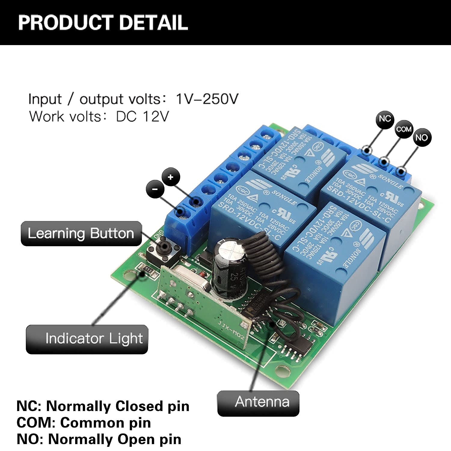
Figure 3: Receiver Board Details
- Learning Button: Used for pairing transmitters and changing operating modes.
- Indicator Light: Provides visual feedback during operation and programming.
- Antenna: Enhances signal reception.
- Screw Terminals: For connecting input power and output devices. Each relay has Normally Closed (NC), Common (COM), and Normally Open (NO) terminals.

Figure 4: Remote Control Details
- Buttons A, B, C, D: Control the corresponding relays on the receiver board.
- Indicator Light: Illuminates when a button is pressed.
- Metal Keychain: For convenient carrying.
3. Technical Specifications
| Specification | Value |
|---|---|
| Model Number | 1204 |
| Input / Output Volts | 1V-250V |
| Work Volts | DC 12V |
| Current Rating | 10 Amps |
| RF Frequency | 433MHz |
| Reception Sensitivity | > 97dBm |
| Chip Code | EV1527 (Learning Code) |
| Remote Control Range | Up to 50 meters (open area) |
| Number of Relays | 4 |
| Relay Lifespan | Over 100,000 uses |
| Connector Type | Screw Terminal |
| Contact Material | Copper Alloy |
| Contact Type | Normally Closed (NC), Common (COM), Normally Open (NO) |
| Mounting Type | Surface Mount |
| Product Dimensions | 2.95 x 2.17 x 1.18 inches |
| Product Weight | 5.93 ounces |
| Batteries (Transmitters) | 2 CR2 batteries (included) |
4. Setup and Wiring
Proper wiring is crucial for the safe and effective operation of your wireless relay switch. Always ensure power is disconnected before making any wiring connections.
Wiring Diagrams:
The receiver board supports various wiring configurations to suit different applications. Below are common examples for connecting lamps, curtain motors, and garage motors.
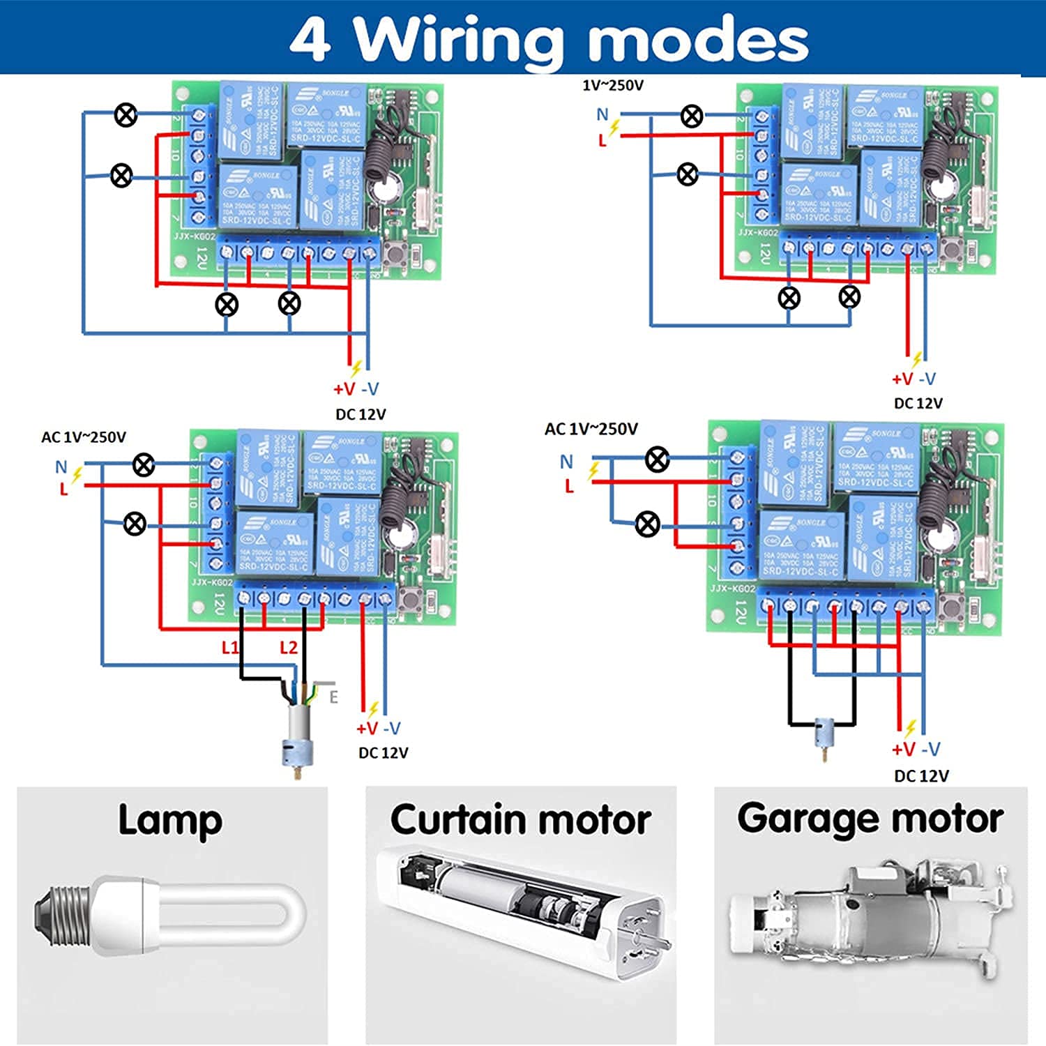
Figure 5: Common Wiring Modes
For specific applications like controlling lights and electric curtains, refer to the detailed connection diagram below.

Figure 6: Remote Control for Lights and Electric Curtains
Pairing Transmitters:
To pair a transmitter with the receiver board, follow these steps based on your desired operating mode. The receiver can store approximately 20 transmitters.

Figure 7: How to Program Operating Modes
- Momentary Mode (Press 1 time): Press the learning button on the receiver board once. The indicator light will turn on. Then, press the desired button on your remote control (e.g., 'A'). The indicator light will flash, confirming successful pairing for momentary mode.
- Toggle Mode (Press 2 times): Press the learning button on the receiver board twice. The indicator light will turn on. Then, press the desired button on your remote control. The indicator light will flash, confirming successful pairing for toggle mode.
- Latched Mode (Press 3 times): Press the learning button on the receiver board three times. The indicator light will turn on. Then, press the desired button on your remote control. The indicator light will flash, confirming successful pairing for latched mode.
- Mixed Mode (Press 4, 5, or 6 times): For advanced mixed modes (e.g., 2 momentary, 2 toggle; or 2 momentary, 2 latched; or 2 toggle, 2 latched), press the learning button 4, 5, or 6 times respectively. Then, press the corresponding remote buttons as instructed by the specific mixed mode configuration.
For a visual guide on programming the remote control switch, please watch the video below:
Video 1: How to Program Remote Control Switch. This video demonstrates the steps to program the receiver board for different operating modes, including momentary, toggle, and latched modes, using the learning button and remote control.
5. Operating Modes
The DieseRC wireless relay switch offers three primary operating modes, which can also be combined into mixed modes, providing flexibility for various control needs.

Figure 8: Operating Mode Explanations
- Momentary Mode: The relay remains activated only while the remote button is pressed and held. Releasing the button deactivates the relay. This is ideal for applications requiring temporary activation, such as a doorbell or a momentary gate opener.
- Toggle Mode: Each press of the remote button toggles the state of the corresponding relay. Press once to activate, press again to deactivate. This mode is suitable for lights or fans where you want to switch them on/off with a single button.
- Latched Mode: Pressing one button activates its corresponding relay and simultaneously deactivates any other active relays in the latched group. For example, pressing button 'A' activates Relay 1, and pressing button 'B' activates Relay 2 while turning off Relay 1. This is useful for selecting between multiple states, like opening or closing a garage door.
- Mixed Modes: The device can be configured to combine different modes across its four channels. For instance, two channels can operate in momentary mode, and the other two in toggle mode, providing highly customized control.
See the relay remote control switch in action, demonstrating its functionality with AC and DC motors, and light control:
Video 2: Relay Remote Control Switch Demonstration. This video showcases the practical application of the relay switch, controlling various devices such as AC motors, DC motors, and lights, illustrating the different operating modes.
6. Maintenance
To ensure the longevity and optimal performance of your DieseRC Wireless Relay Remote Control Switch, consider the following maintenance tips:
- Keep Clean: Regularly wipe the receiver board and remote controls with a dry, soft cloth to prevent dust and debris accumulation.
- Avoid Moisture: Protect the device from water and high humidity, as moisture can damage electronic components.
- Battery Replacement: If the remote control's range decreases or its indicator light dims, replace the CR2 batteries. Ensure correct polarity.
- Secure Connections: Periodically check all screw terminal connections to ensure they are tight and secure, preventing loose wires and potential electrical issues.
- Operating Environment: Use the device within its specified temperature and humidity ranges to prevent premature wear.
7. Troubleshooting
If you encounter issues with your DieseRC Wireless Relay Remote Control Switch, refer to the following common problems and their solutions:
- Remote Control Not Responding:
- Check the remote control battery. Replace if necessary.
- Ensure the remote is within the effective operating range (up to 50 meters in open areas).
- Verify that the receiver board is powered on and its indicator light is active.
- Re-pair the transmitter with the receiver board following the instructions in Section 4.
- Relay Not Activating/Deactivating Correctly:
- Confirm that the wiring connections to the relay terminals (NO, COM, NC) are correct for your application.
- Check the operating mode programmed for the relay (Momentary, Toggle, Latched). Incorrect mode can lead to unexpected behavior.
- Ensure the connected device is functioning properly and its power supply is adequate.
- Short Range or Signal Interference:
- Ensure the receiver's antenna is not obstructed or damaged.
- Minimize obstacles (thick walls, metal structures) between the transmitter and receiver.
- Avoid placing the receiver near other strong RF signal sources that might cause interference.
- Resetting the Receiver: If persistent issues occur or you wish to clear all paired transmitters, press the learning button on the receiver board 8 times. The indicator light will flash, confirming the reset. After a reset, all transmitters must be re-paired.
8. Warranty and Support
DieseRC is committed to providing high-quality products and excellent customer service. Your product is covered by a 1-year warranty from the date of purchase, ensuring peace of mind regarding its quality and performance.
For any technical assistance, troubleshooting, or warranty claims, please contact our support team:
- Service Email: dieseelectronic@163.com
This document provides a simplified HTML version of the user manual. For the official PDF user manual, please refer to the link provided with your product or on the product's Amazon page.


