Shipenophy KT87N
KT87N Mini Digital Clamp Multimeter User Manual
Model: KT87N | Brand: Shipenophy
1. Introduction
This user manual provides detailed instructions for the safe and effective operation of the Shipenophy KT87N Mini Digital Clamp Multimeter. This versatile instrument is designed for measuring AC/DC voltage, AC current, resistance, and for diode testing and continuity checks. Its compact size and comprehensive features make it an essential tool for electricians, hobbyists, and DIY enthusiasts.

Figure 1.1: The KT87N Mini Digital Clamp Multimeter shown with its accompanying test leads. This image provides an overview of the device and its primary accessories.
2. Safety Information
Always observe the following safety precautions when using the KT87N multimeter to prevent personal injury or damage to the instrument.
- Do not exceed the maximum input values specified for each measurement range.
- Ensure the function switch is in the correct position before making any measurements.
- Do not use the meter if it appears damaged or if the insulation on the test leads is compromised.
- Exercise extreme caution when working with live circuits.
- Always disconnect power to the circuit before measuring resistance or continuity.
- Replace batteries promptly when the low battery indicator appears.
3. Product Components and Features
Familiarize yourself with the main components and features of your KT87N multimeter.
- Clamp Jaw: Used for non-contact AC current measurement.
- Function Switch: Rotary switch to select measurement functions (ACV, DCV, ACA, Resistance, Diode, Continuity).
- LCD Display: Large screen for clear digital readings, with a maximum display of 1999.
- "DATA HOLD" Button: Freezes the current reading on the display.
- "COM" Jack: Common input jack for test leads (negative).
- "VΩ" Jack: Input jack for voltage, resistance, diode, and continuity measurements (positive).
- Low Battery Indicator: Alerts when battery replacement is needed.
- Overload Protection: Built-in safety feature to prevent damage from excessive input.
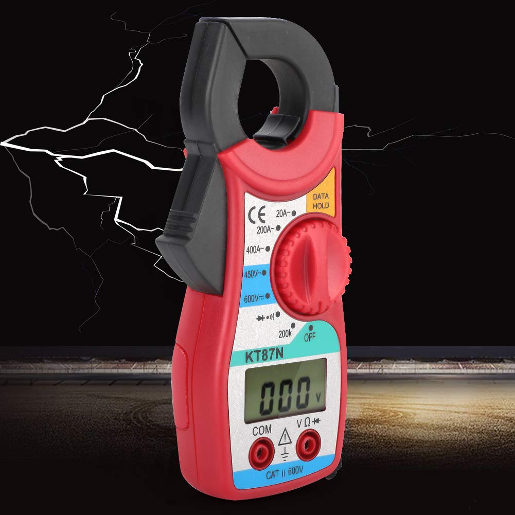
Figure 3.1: Side view of the KT87N multimeter, highlighting the clamp jaw mechanism used for current measurements.

Figure 3.2: Another side profile of the KT87N multimeter, illustrating its compact design and ergonomic grip.
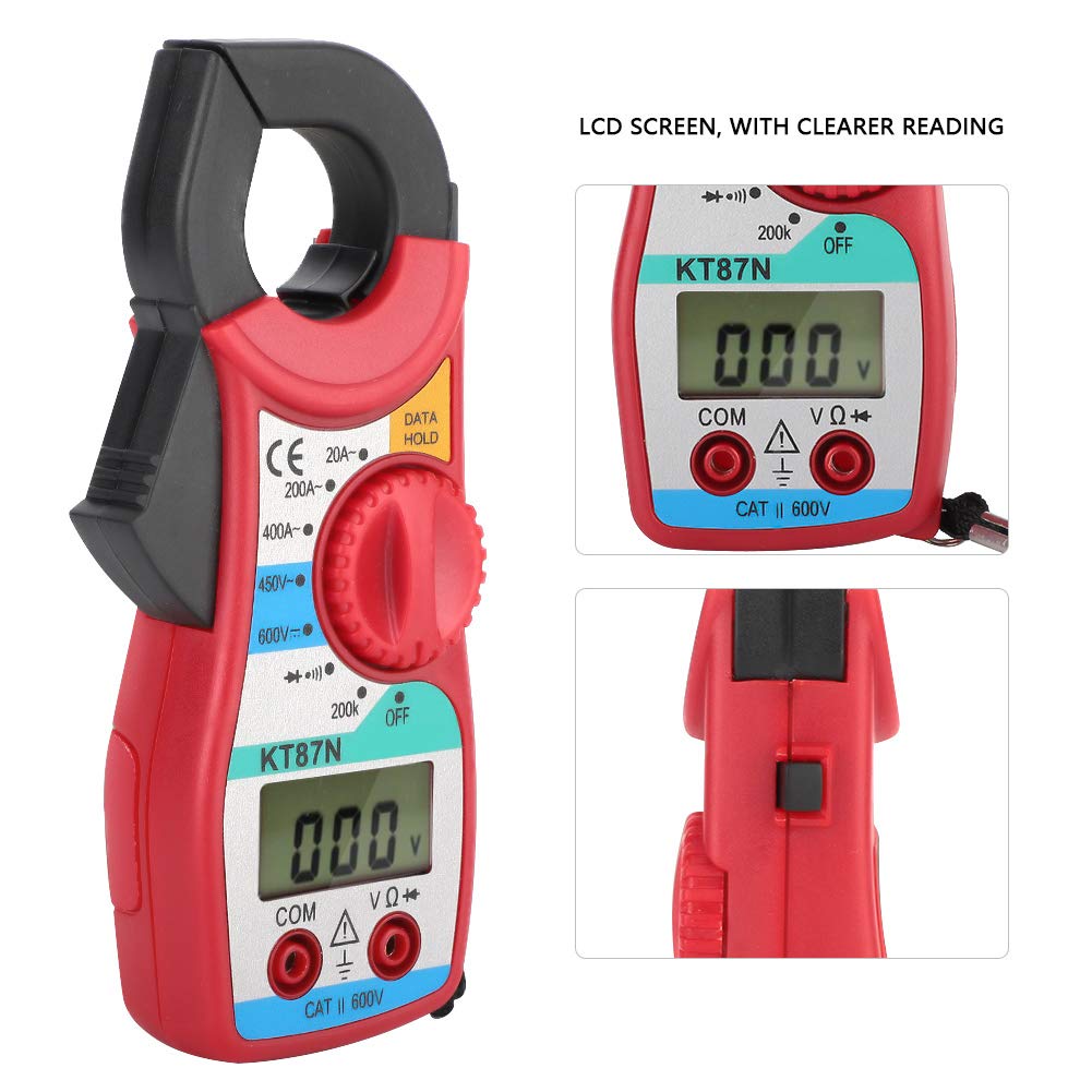
Figure 3.3: A detailed view of the KT87N's LCD screen and the rotary function switch, indicating various measurement modes and the "DATA HOLD" button.
4. Setup
4.1. Battery Installation
The KT87N multimeter is powered by batteries. To install or replace batteries:
- Ensure the multimeter is turned OFF.
- Locate the battery compartment cover on the back of the unit.
- Use a screwdriver to open the battery compartment.
- Insert new batteries, observing the correct polarity (+/-).
- Replace the battery compartment cover and secure it.
4.2. Connecting Test Leads
For most measurements (voltage, resistance, diode, continuity), you will need to connect the test leads.
- Insert the black test lead into the "COM" (common) jack.
- Insert the red test lead into the "VΩ" jack.

Figure 4.1: The red and black test leads, essential accessories for various electrical measurements with the KT87N multimeter.

Figure 4.2: The KT87N multimeter with the red and black test leads properly connected to their respective input jacks, ready for use.
5. Operating Instructions
5.1. Measuring AC Current (Clamp Function)
The clamp function allows for non-contact measurement of AC current.
- Turn the function switch to the desired AC current range (20A or 400A).
- Open the clamp jaw by pressing the trigger.
- Enclose only one conductor of the circuit within the clamp jaw. Do not clamp around multiple conductors.
- Read the current value on the LCD display.

Figure 5.1: The KT87N multimeter demonstrating its clamp function, measuring current by enclosing a single electrical cable within its jaw.
5.2. Measuring DC Voltage
To measure DC voltage:
- Connect the black test lead to "COM" and the red test lead to "VΩ".
- Turn the function switch to the DC Voltage range (e.g., 600V DC).
- Connect the test probes across the component or circuit to be measured.
- Read the voltage value on the LCD display.
5.3. Measuring AC Voltage
To measure AC voltage:
- Connect the black test lead to "COM" and the red test lead to "VΩ".
- Turn the function switch to the AC Voltage range (e.g., 450V AC).
- Connect the test probes across the component or circuit to be measured.
- Read the voltage value on the LCD display.
5.4. Measuring Resistance
To measure resistance:
- Ensure the circuit is de-energized before measuring resistance.
- Connect the black test lead to "COM" and the red test lead to "VΩ".
- Turn the function switch to the Resistance range (e.g., 200KΩ).
- Connect the test probes across the component whose resistance you want to measure.
- Read the resistance value on the LCD display.
5.5. Diode Test
To perform a diode test:
- Ensure the circuit is de-energized.
- Connect the black test lead to "COM" and the red test lead to "VΩ".
- Turn the function switch to the Diode test position.
- Connect the red probe to the anode and the black probe to the cathode of the diode.
- The display will show the forward voltage drop. Reverse the probes; the display should show "OL" (open loop) for a good diode.
5.6. Continuity Test
To check for continuity:
- Ensure the circuit is de-energized.
- Connect the black test lead to "COM" and the red test lead to "VΩ".
- Turn the function switch to the Continuity test position (often shared with diode test, indicated by a buzzer symbol).
- Connect the test probes across the circuit or component.
- If there is continuity (low resistance), the buzzer will sound. The display will show the resistance value.
5.7. Data Hold Function
Press the "DATA HOLD" button to freeze the current reading on the LCD display. Press it again to release the hold and resume live readings.
6. Maintenance
6.1. Cleaning
To clean the multimeter, wipe the case with a damp cloth and a mild detergent. Do not use abrasives or solvents.
6.2. Battery Replacement
When the low battery indicator appears on the display, replace the batteries as described in the "Battery Installation" section (4.1).
6.3. Storage
If the multimeter is not used for an extended period, remove the batteries to prevent leakage and damage to the unit. Store the device in a cool, dry place, away from direct sunlight and extreme temperatures.
7. Troubleshooting
| Problem | Possible Cause | Solution |
|---|---|---|
| No display or dim display | Dead or low batteries | Replace batteries. |
| "OL" (Overload) displayed | Input value exceeds selected range or meter's maximum capacity. | Select a higher range or ensure input is within specifications. |
| Incorrect readings | Incorrect function selected; Poor test lead connection; Damaged test leads. | Verify function switch position; Ensure leads are firmly connected; Inspect and replace damaged leads. |
| No continuity beep | Open circuit; High resistance; Incorrect function. | Check circuit for breaks; Ensure resistance is low enough for continuity; Verify function switch. |
8. Specifications
The following are the technical specifications for the KT87N Mini Digital Clamp Multimeter:
- Model: KT87N
- Display: LCD, Max. 1999 counts
- DC Voltage: Up to 600V
- AC Voltage: Up to 450V
- AC Current: 20A / 400A
- Resistance: Up to 200KΩ
- Diode Test: Yes
- Continuity Buzzer: Yes
- Data Hold: Yes
- Overload Protection: Yes
- Low Battery Indicator: Yes
- Power Source: Battery (specific type not provided, assuming common AA/AAA or 9V)
- Dimensions: Approximately 150mm / 5.9in (length), 63mm / 2.5in (width), 28mm / 1.1in (thickness)
- Origin: China

Figure 8.1: The KT87N multimeter with its approximate dimensions (length, width, thickness) clearly indicated for reference.
9. Warranty and Support
For warranty information and technical support, please refer to the contact details provided by your retailer or the manufacturer, Shipenophy. Keep your purchase receipt as proof of purchase.
no relevant documents
Ask a question about this manual
Ask about setup, troubleshooting, compatibility, parts, safety, or missing instructions. Manuals+ will review the question and use this page’s manual context to help answer it.