Introduction
This manual provides detailed instructions for the installation, operation, and maintenance of the BOOTOP PIN Complete Wiring Harness Kit. This kit is designed for various Chinese-made electric start upright engines ranging from 49cc to 125cc, commonly found in ATVs, Quads, Pit Bikes, and Dirt Bikes.
Please read this manual thoroughly before attempting installation to ensure proper function and safety. Professional installation is highly recommended.
Product Components
The BOOTOP PIN Complete Wiring Harness Kit includes the following components:
- 1 x ATV Wire Harness
- 1 x CDI (5-Pin AC)
- 1 x Ignition Coil with Lead
- 1 x Spark Plug
- 1 x Solenoid Relay
- 1 x Rectifier (Voltage Regulator)
- 1 x Stator (Magneto Generator)
- 1 x Ignition Switch (with 2 keys, waterproof)
- 1 x Upgraded Multi-functional ATV Switch
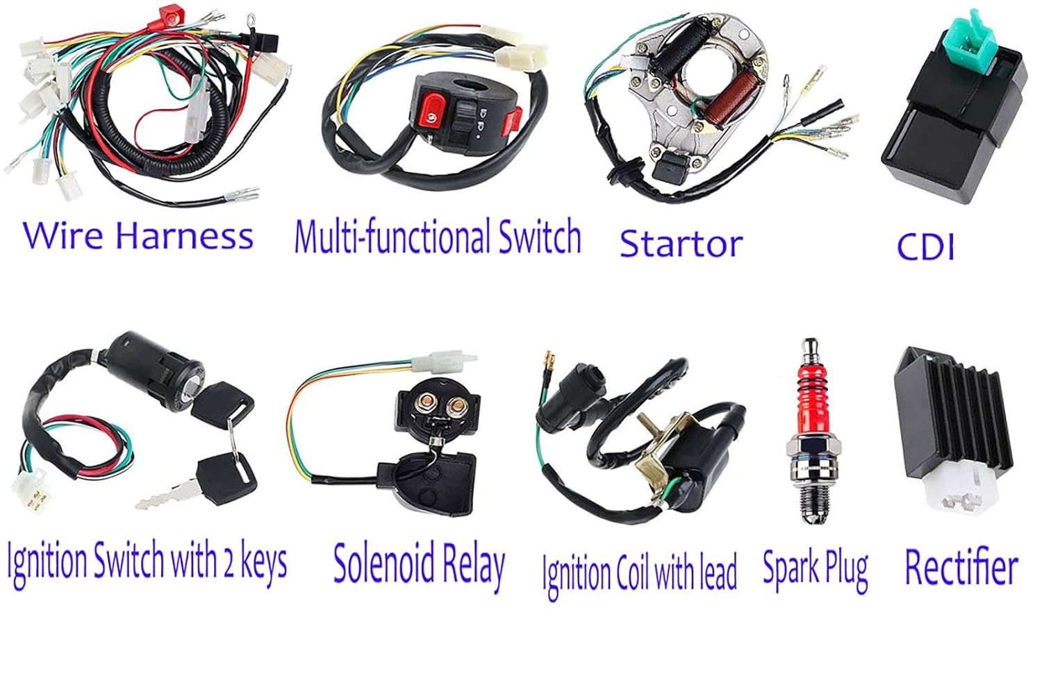
Image: Labeled individual components of the wiring harness kit, including the wire harness, multi-functional switch, stator, CDI, ignition switch with keys, solenoid relay, ignition coil with lead, spark plug, and rectifier.

Image: A comprehensive view of all components included in the BOOTOP PIN ATV Wiring Harness Kit, neatly arranged on a white background.
Compatibility
This wiring harness kit is compatible with most Chinese-made electric start upright engines from 49cc, 50cc, 70cc, 80cc, 90cc, 100cc, 110cc, to 125cc. It is suitable for various vehicles including:
- ATV / Quad
- Kawasaki KLX
- Coolster
- Scooter
- 4 Wheelers
- Buggy
- Dirt Bike
- Go Kart
- Pit Bike
- Motowork
Compatible Brands include: Kazuma, Atomik, Pitpro, Hummer, Orion, Xmoto, Lei, DMX, SWD, TDR, DDR, Tommahawk, Monsoon, Grudge, Bull, Trooper, Hunter, Motox, Trojan, Blitz, Crusade, Link, Bigfoot, Kuda, Motoworks, Nitrous, Reign, Fury, Prox, Raider, Zongshen, Loncin, Ducar, Lifan, Thumpster, Thumbstar, Chongqing.
Important Note: This kit is NOT compatible with GY6 motorbikes or other 200cc - 250cc Zongshen Lifan ATV/QUAD models that use a different stator or CDI. It is also not designed for GY6 150cc engines. Please verify your vehicle's specifications before purchase.
Important Safety Information
- Professional Installation Recommended: Due to the complexity of electrical systems, professional installation by a qualified mechanic is highly recommended. Incorrect assembly can lead to electrical shorts, component damage, or fire.
- Verify Compatibility: Always confirm that this harness kit matches your vehicle's model and engine type before installation.
- Wiring Diagram: Always refer to the provided wiring diagram and your vehicle's specific service manual before connecting any components.
- Polarity: The red wire in this harness is the positive pole, and the black wire is the negative pole. Ensure correct polarity during connection.
- Old Vehicles: Exercise caution when installing on older vehicles to prevent potential short circuits due to existing wiring conditions.
Setup and Installation
Installing the BOOTOP PIN wiring harness kit requires careful attention to detail. Follow these general steps, always cross-referencing with the wiring diagram and your vehicle's specific requirements.
- Preparation:
- Disconnect the vehicle's battery to prevent electrical shock or damage.
- Carefully remove the old wiring harness and associated electrical components, noting their original connections.
- Lay out all new components from the kit and familiarize yourself with each part.
- Wiring Harness Placement:
Route the new main wiring harness through the vehicle's frame, ensuring it is secured and away from moving parts or heat sources. Connect the main harness to the battery (red to positive, black to negative).

Image: The complete wiring harness kit laid out, showing the main harness and all connected components, providing a visual guide for routing.
- Component Connection:
Connect each component to its corresponding connector on the main wiring harness. Refer to the wiring diagram below for correct connections.
- Stator: Connect the stator wires to the appropriate harness connector.
- CDI: Plug the 5-pin AC CDI unit into its designated connector.
- Ignition Coil: Connect the ignition coil lead to the spark plug and the coil's wires to the harness.
- Solenoid Relay: Connect the solenoid relay.
- Rectifier (Voltage Regulator): Connect the rectifier to regulate voltage.
- Ignition Switch: Install the ignition switch and connect its wires.
- Multi-functional ATV Switch: Connect the multi-functional switch for lights, engine kill, etc.
- Spark Plug: Install the new spark plug and connect the ignition coil lead.
- Wiring Diagram Reference:
Use the basic wiring diagram provided to ensure all connections are made correctly. Pay close attention to wire colors and connector types.

Image: A basic wiring diagram illustrating the connections for a Chinese electric start system, showing components like the magneto stator, CDI, coil, regulator, starter motor, solenoid, key switch, safety switch, engine kill switch, and battery.
- Final Checks:
- Double-check all connections for tightness and correct placement.
- Ensure no wires are pinched, frayed, or exposed.
- Reconnect the battery.
Operation and Testing
After installation, perform the following tests to ensure the electrical system is functioning correctly:
- Ignition System Test:
- Turn the ignition key to the "ON" position.
- Attempt to start the engine. Listen for the starter motor engaging and the engine attempting to fire.
- If the engine does not start, check for spark at the spark plug.
- Lighting and Switches Test:
- Test all lights (headlights, taillights, brake lights, turn signals if applicable).
- Verify the functionality of the engine kill switch and any other switches on the multi-functional ATV switch.
- Charging System Test:
- With the engine running, use a multimeter to check the voltage across the battery terminals. It should be above 13.5V, indicating the rectifier and stator are charging the battery.
If any component does not function as expected, refer to the Troubleshooting section.
Maintenance
Regular maintenance of your vehicle's electrical system can extend the life of the wiring harness and components.
- Inspect Wiring: Periodically check the wiring harness for any signs of wear, fraying, cracks, or heat damage. Ensure all connections are secure.
- Clean Connections: Keep electrical connectors clean and free of dirt, moisture, and corrosion. Dielectric grease can be applied to prevent corrosion.
- Battery Maintenance: Ensure the battery terminals are clean and tight. Check battery fluid levels if applicable.
- Component Check: Occasionally inspect the CDI, rectifier, ignition coil, and stator for any visible damage or loose connections.
Troubleshooting
If you encounter issues after installing the wiring harness kit, consider the following common problems and solutions:
- No Power / Engine Won't Start:
- Check battery connections and ensure the battery is charged.
- Verify all harness connectors are fully seated and secure.
- Inspect the ignition switch and engine kill switch for proper function.
- Check the fuse (if present in your system) for continuity.
- No Spark at Spark Plug:
- Ensure the spark plug is correctly installed and the ignition coil lead is firmly attached.
- Test the ignition coil for resistance according to your vehicle's service manual.
- Check the CDI unit connections and consider testing the CDI if possible.
- Verify stator output (requires a multimeter and knowledge of expected values).
- Lights Not Working / Battery Not Charging:
- Check connections to the rectifier (voltage regulator) and stator.
- Test the rectifier output with a multimeter.
- Inspect the multi-functional switch for proper operation.
- Incorrect Wire Colors:
Some older vehicles or specific models may have different wire color codes. Always prioritize the wiring diagram and connector shapes over color alone. If unsure, consult a professional mechanic.
If troubleshooting steps do not resolve the issue, it is recommended to seek assistance from a qualified mechanic.
Specifications
| Feature | Specification |
|---|---|
| Product Model Number | atv 110 wiring harness |
| Product Dimensions | 2.8 x 2 x 0.5 inches (packaging) |
| Item Weight | 2 Pounds |
| Material | Lead (components) |
| CDI Type | 5-Pin AC |
| Ignition Switch | Waterproof, 2 keys included |
| Engine Compatibility | 49cc, 50cc, 70cc, 80cc, 90cc, 100cc, 110cc, 125cc electric start upright engines |
Warranty Information
Specific warranty details for the BOOTOP PIN Complete Wiring Harness Kit are not provided in this manual. For information regarding warranty coverage, terms, and conditions, please refer to the product packaging or contact BOOTOP PIN customer support directly.
Generally, products may be eligible for return, replacement, or refund requests if you are not satisfied. Please retain your proof of purchase for any warranty claims.
Customer Support
For technical assistance, questions regarding installation, or any issues with your BOOTOP PIN Complete Wiring Harness Kit, please contact BOOTOP PIN customer support.
You can typically find contact information on the product packaging or through the retailer where the product was purchased. When contacting support, please have your product model number ("atv 110 wiring harness") and purchase details ready.


