Introduction
Thank you for choosing the Xprite Blue LED Emergency Strobe Lights Kit. This manual provides detailed instructions for the proper installation, operation, and maintenance of your new strobe lights. Please read this manual thoroughly before installation and use to ensure safe and efficient operation.
This kit is designed to enhance vehicle visibility for emergency services, public safety, and volunteer vehicles, featuring high-intensity blue LEDs for clear signaling.
Safety Information
- Always disconnect the vehicle's battery before beginning any electrical installation.
- Ensure all wiring connections are secure and properly insulated to prevent short circuits.
- Verify local and provincial/state laws regarding the use of emergency vehicle lighting before installation and operation. Misuse may result in fines or legal action.
- Do not stare directly into the LED lights when they are active, as this may cause temporary vision impairment.
- Mount lights securely to prevent detachment during vehicle operation.
Package Contents
The Xprite Blue LED Emergency Strobe Lights Kit includes the following components:
- 10 x Blue LED Strobe Light Modules
- Mounting Gaskets (10 pieces)
- Mounting Screws (20 pieces)
- Wiring Harness (integrated with each module)

Specifications
| Feature | Specification |
|---|---|
| Model Number | 52026S-12-B-10PC |
| Rated Lifetime | Over 50,000 hours |
| Operating Voltage | 10-30V DC |
| Number of LEDs per Module | 12 LEDs |
| Strobe Patterns | 18 Flash Patterns (with last pattern memory) |
| Cable Length | 8.2 ft (approx. 2.5 meters) |
| Module Dimensions (L x W) | 3.99 in x 1.11 in (approx. 10.1 cm x 2.8 cm) |
| Lens Material | Acrylic |
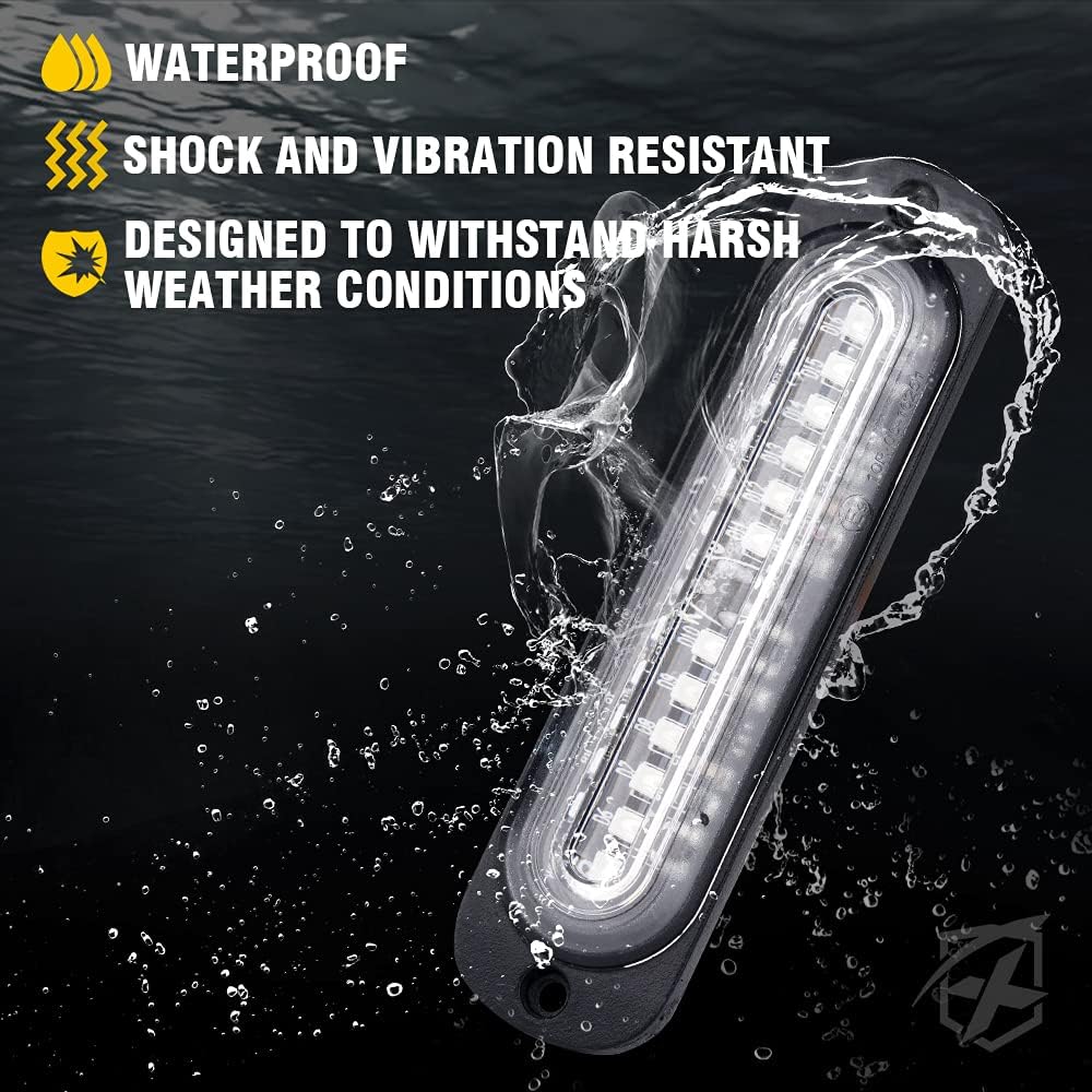
| Special Features | Waterproof, Shock and Vibration Resistant |

Installation (Setup)
The Xprite LED Strobe Lights are designed for flush or surface mounting. Follow these steps for proper installation:
- Choose Mounting Location: Select a flat, secure surface on your vehicle's grille, bumper, or other suitable area. Ensure the location allows for optimal light visibility and does not obstruct vehicle functions.
- Mark Drilling Points: Place the light module with its gasket on the chosen surface and mark the two screw hole locations.
- Drill Pilot Holes: Using an appropriate drill bit size for the provided screws, drill pilot holes at the marked locations. For flush mounting, you may need to cut an opening for the light body to sit recessed.
- Secure the Module: Position the gasket and light module over the pilot holes. Secure the module using the provided mounting screws. Do not overtighten.
- Repeat for all Modules: Install all 10 light modules following the same procedure.

Wiring Diagram and Connections
Each strobe light module has five wires for connection. Proper wiring is crucial for functionality and pattern synchronization.
- Red Wire: Positive (+) power input (10-30V DC). Connect to a fused 12V/24V power source.
- Black Wire: Negative (-) ground. Connect to a reliable chassis ground point.
- Yellow Wire: Pattern Change. Briefly touch this wire to the Red (Positive) wire to cycle through the 18 flash patterns.
- White Wire: Synchronization (Sync). Connect the White wires of all modules together to synchronize their flash patterns.
- Gray Wire: Solid / Steady Mode. Connect this wire to the Red (Positive) wire to activate a steady-on light mode. Disconnect for strobe patterns.
Important Wiring Notes:
- Ensure all connections are soldered or crimped securely and protected with heat shrink tubing or electrical tape.
- Use appropriate gauge wiring for your application to prevent overheating.
- Consider installing an inline fuse (not included) on the main positive power line for added protection.
Operation
Once properly installed and wired, operate your Xprite LED Strobe Lights as follows:
- Power On/Off: Apply 10-30V DC power to the Red (+) and Black (-) wires to turn the lights on. Disconnect power to turn them off.
- Change Flash Patterns: Briefly touch the Yellow wire to the Red (Positive) wire. Each brief touch will advance to the next of the 18 available flash patterns. The lights feature a last pattern memory function, recalling the last selected pattern when powered on.
- Synchronization: If multiple modules are connected via their White (Sync) wires, they will flash in unison according to the selected pattern.
- Solid/Steady Mode: To activate a continuous, non-flashing light, connect the Gray wire to the Red (Positive) wire. Disconnect the Gray wire from the Red wire to return to strobe patterns.


Maintenance
The Xprite LED Strobe Lights are designed for durability and require minimal maintenance. Follow these guidelines to ensure long-lasting performance:
- Regular Cleaning: Periodically clean the lens of the light modules with a soft cloth and mild soap and water. Avoid abrasive cleaners or solvents that could damage the lens.
- Inspect Wiring: Annually inspect all wiring connections for signs of wear, corrosion, or damage. Repair or replace any compromised wiring immediately.
- Check Mounting: Ensure all mounting screws remain tight and the modules are securely fastened to the vehicle. Retighten if necessary.
- Waterproof Integrity: While the lights are waterproof, avoid directing high-pressure water jets directly at the modules during vehicle washing, especially at close range.
Troubleshooting
| Problem | Possible Cause | Solution |
|---|---|---|
| Lights do not turn on. | No power, incorrect wiring, blown fuse. | Check power connection (Red wire), ground connection (Black wire), and vehicle fuse. Ensure voltage is within 10-30V DC. |
| Lights do not change patterns. | Yellow wire not connected or faulty, Gray wire connected to positive. | Ensure Yellow wire is briefly touched to positive. Disconnect Gray wire from positive if it's in solid mode. |
| Lights are not synchronized. | White (Sync) wires not properly connected between modules. | Verify all White wires are securely connected together. |
| Moisture inside the light module. | Seal compromise, extreme temperature changes. | While lights are waterproof, prolonged exposure to high-pressure water or extreme conditions can sometimes affect seals. Inspect for physical damage. If persistent, contact support. |
Warranty and Support
Xprite products are designed for quality and performance. For warranty information, technical support, or replacement parts, please refer to the official Xprite website or contact their customer service directly. Keep your purchase receipt as proof of purchase.
For further assistance, visit: www.xpriteusa.com


