Bridgold CD4051
CD4051 CMOS Analog Multiplexer/Demultiplexer User Manual
Model: CD4051
1. Introduction
The CD4051B is a high-performance CMOS analog multiplexer/demultiplexer designed for use in a wide range of applications requiring analog signal switching. It features a single 8-channel configuration, allowing one of eight input signals to be routed to a common output, or vice-versa, based on binary control inputs. This device is part of the CD4000 series of CMOS integrated circuits, known for their low power consumption and wide operating voltage range.
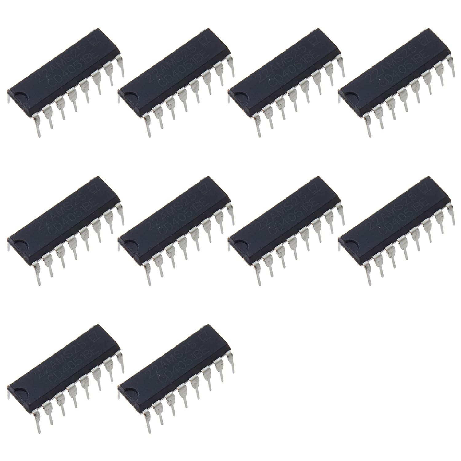
Figure 1: A set of ten CD4051 integrated circuits in DIP-16 package.
2. Key Features
- Wide Range of Digital Levels: Supports digital control signals from 3V to 20V, ensuring compatibility with various logic families.
- Low ON Resistance: Typically 125Ω over a 15VP-P signal input range when VDD-VEE = 18V, minimizing signal distortion.
- High OFF Resistance: Channel leakage of ±100pA (Typ) at VDD-VEE = 18V, ensuring minimal crosstalk and signal bleed-through when channels are off.
- Binary Address Decoding on Chip: Simplifies control logic by directly interpreting binary inputs (A, B, C) for channel selection.
- 100% Tested for Quiescent Current at 20V: Guarantees reliable low power operation across the specified voltage range.
3. Setup and Pinout
The CD4051B is supplied in a standard 16-pin Dual In-line Package (DIP-16). Proper identification of pins is crucial for correct circuit integration.
3.1 Pin Identification
Pin 1 is typically indicated by a dot or a notch on the package. Pins are numbered counter-clockwise from Pin 1 when viewed from the top.

Figure 2: Top view of the CD4051 IC, showing the orientation notch.

Figure 3: Bottom view of the CD4051 IC, showing the pin arrangement.
3.2 Basic Connections
- Power Supply (VDD, VSS, VEE): Connect VDD to the positive supply voltage (e.g., +5V to +18V). Connect VSS to ground (0V). For analog signals that swing below ground, VEE should be connected to a negative supply voltage (e.g., -5V). If only positive analog signals are used, VEE can be connected to VSS.
- Control Inputs (A, B, C): These are binary inputs that select one of the eight channels. Apply standard logic levels (0V or VDD) to these pins.
- Inhibit Input (INH): When INH is high (VDD), all channels are turned off, regardless of the A, B, C inputs. When INH is low (VSS), the multiplexer operates normally.
- Common Output/Input (COM): This pin is the common connection for all eight channels.
- Channel Inputs/Outputs (X0-X7): These are the individual analog channels. Depending on the mode (multiplexer or demultiplexer), these can be inputs or outputs.
4. Operating Principles
The CD4051B functions as an 8-channel analog multiplexer or demultiplexer. In multiplexer mode, it selects one of eight analog input signals (X0-X7) and routes it to a single common output (COM). In demultiplexer mode, a single analog input signal applied to COM is routed to one of the eight output channels (X0-X7).
4.1 Channel Selection
Channel selection is controlled by the three binary address inputs: A (LSB), B, and C (MSB). The truth table below illustrates how these inputs select the active channel:
| C (MSB) | B | A (LSB) | Selected Channel |
|---|---|---|---|
| 0 | 0 | 0 | X0 |
| 0 | 0 | 1 | X1 |
| 0 | 1 | 0 | X2 |
| 0 | 1 | 1 | X3 |
| 1 | 0 | 0 | X4 |
| 1 | 0 | 1 | X5 |
| 1 | 1 | 0 | X6 |
| 1 | 1 | 1 | X7 |
Table 1: Channel Selection Truth Table (INH = 0)
4.2 Inhibit Function
The Inhibit (INH) input provides a master switch for the multiplexer. When INH is asserted high (logic 1), all channels are turned off, effectively disconnecting COM from all X inputs/outputs. This feature is useful for disabling the device or for implementing break-before-make switching in certain applications.
5. Specifications
The following table details the key electrical and physical specifications for the CD4051B:
| Parameter | Value |
|---|---|
| Device Type | CMOS Analog Multiplexer/Demultiplexer |
| Channels | Single 8-Channel |
| Control Inputs | A, B, C (Binary), Inhibit (INH) |
| Digital Level Range | 3V to 20V |
| Typical ON Resistance | 125Ω (at VDD-VEE = 18V, 15VP-P signal) |
| Typical OFF Resistance Channel Leakage | ±100pA (at VDD-VEE = 18V) |
| Package Type | DIP-16 |
| Package Dimensions | 4.96 x 2.72 x 0.28 inches |
| Weight | 0.32 ounces |
| Manufacturer | Bridgold |
6. Maintenance
The CD4051B is a robust integrated circuit designed for long-term reliability. Minimal maintenance is required, but adherence to best practices for handling electronic components will ensure optimal performance and longevity.
- Static Discharge Protection: CMOS devices are sensitive to electrostatic discharge (ESD). Always handle the ICs in an ESD-safe environment, using grounded wrist straps and mats. Store unused ICs in anti-static bags or conductive foam.
- Storage: Store ICs in a dry, cool environment, away from direct sunlight and extreme temperatures. Keep them in their original packaging or anti-static containers until ready for use.
- Cleaning: If cleaning is necessary, use a soft, dry brush or compressed air to remove dust. Avoid using liquid cleaners directly on the component.
- Soldering: When soldering, use appropriate soldering techniques to prevent overheating the component. Excessive heat can damage the internal circuitry.
7. Troubleshooting
If the CD4051B is not functioning as expected, consider the following common issues and troubleshooting steps:
- No Output/Incorrect Channel Selection:
- Verify power supply connections (VDD, VSS, VEE) are correct and within the specified voltage range.
- Check the Inhibit (INH) pin. If INH is high, all channels will be off. Ensure it is low for normal operation.
- Confirm the binary control inputs (A, B, C) are providing the correct logic levels for the desired channel. Use a multimeter or oscilloscope to verify.
- Ensure all pins are properly seated in the socket or correctly soldered to the PCB, with no short circuits or open connections.
- Signal Distortion/Attenuation:
- Check if the analog signal voltage range exceeds the VDD/VEE limits. The analog signal should not exceed VDD or go below VEE.
- Ensure the power supply is stable and free from excessive noise. Add decoupling capacitors (e.g., 0.1µF ceramic) close to the VDD and VSS pins.
- Verify that the load impedance is not too low, which could cause excessive current draw or voltage drop across the ON resistance.
- Device Overheating:
- Check for short circuits on the output or input channels.
- Ensure the power supply voltage is not exceeding the maximum rating (20V).
8. Warranty and Support
For specific warranty information and technical support regarding your Bridgold CD4051 integrated circuits, please refer to the documentation provided with your purchase or contact the manufacturer directly. Details for Bridgold support can typically be found on their official website or through your point of purchase.