1. Introduction
The Flight Model QS10-S is a high-current, anti-spark battery connector designed for applications requiring reliable power transfer and protection against initial spark generation during connection. This manual provides essential information for the safe and effective use of your QS10-S connectors, including setup, operation, maintenance, and specifications.
2. Safety Instructions
Please read and understand all safety instructions before handling or using the QS10-S connectors. Failure to follow these instructions may result in injury, property damage, or product malfunction.
- High Current Warning: These connectors are designed for high current applications (up to 180A). Improper handling can lead to severe electrical shock, burns, or fire.
- Professional Installation Recommended: Soldering and electrical connections should be performed by individuals with appropriate knowledge and experience.
- Polarity: Always observe correct polarity when connecting batteries and devices. Incorrect polarity will cause damage to components. The QS10-S connectors are designed with clear positive (+) and negative (-) markings.
- Insulation: Ensure all connections are properly insulated to prevent short circuits.
- Ventilation: Work in a well-ventilated area, especially when soldering.
- Inspection: Regularly inspect connectors for signs of wear, damage, or corrosion. Do not use damaged connectors.
- Children and Pets: Keep connectors and tools out of reach of children and pets.
3. Package Contents
Verify that all components are present and undamaged upon opening the package.
- QS10-S Male Connector (with anti-spark pin)
- QS10-S Female Connector

Image 1: A complete set of Flight Model QS10-S anti-spark battery connectors, showing both male and female components.
4. Setup and Installation
Proper installation is crucial for the performance and safety of the QS10-S connectors. This section outlines the steps for soldering and assembling the connectors.
4.1 Required Tools and Materials
- High-wattage soldering iron (100W or more recommended for large gauge wires)
- Solder (lead-free or leaded, suitable for electrical connections)
- Flux (optional, but recommended for clean joints)
- Wire strippers
- Heat shrink tubing (appropriate size for your wires)
- Heat gun or lighter (for heat shrink)
- Vise or helping hands (to hold connectors/wires)
4.2 Soldering Procedure
- Prepare Wires: Strip approximately 8-10mm of insulation from the ends of your battery and device wires. Ensure the wire strands are clean and twisted.
- Pre-tin Wires and Connectors: Apply a small amount of solder to the stripped wire ends and the solder cups of the QS10-S connectors. This ensures a better bond.
- Attach Heat Shrink: Slide a piece of heat shrink tubing onto each wire before soldering. This is a common mistake to avoid.
- Solder Connections:
- Carefully solder the positive (+) wire to the positive (+) terminal of the connector and the negative (-) wire to the negative (-) terminal.
- For the male connector, the anti-spark pin is typically connected to the negative (-) terminal. Ensure the main negative pin is soldered first, then the smaller anti-spark pin.
- Heat the solder cup and the pre-tinned wire simultaneously, then apply solder until it flows smoothly and creates a strong, shiny joint. Avoid cold solder joints.
- Insulate Connections: Once the solder joints have cooled, slide the heat shrink tubing over the soldered connections and apply heat with a heat gun or lighter until it shrinks tightly around the joint, providing insulation and strain relief.
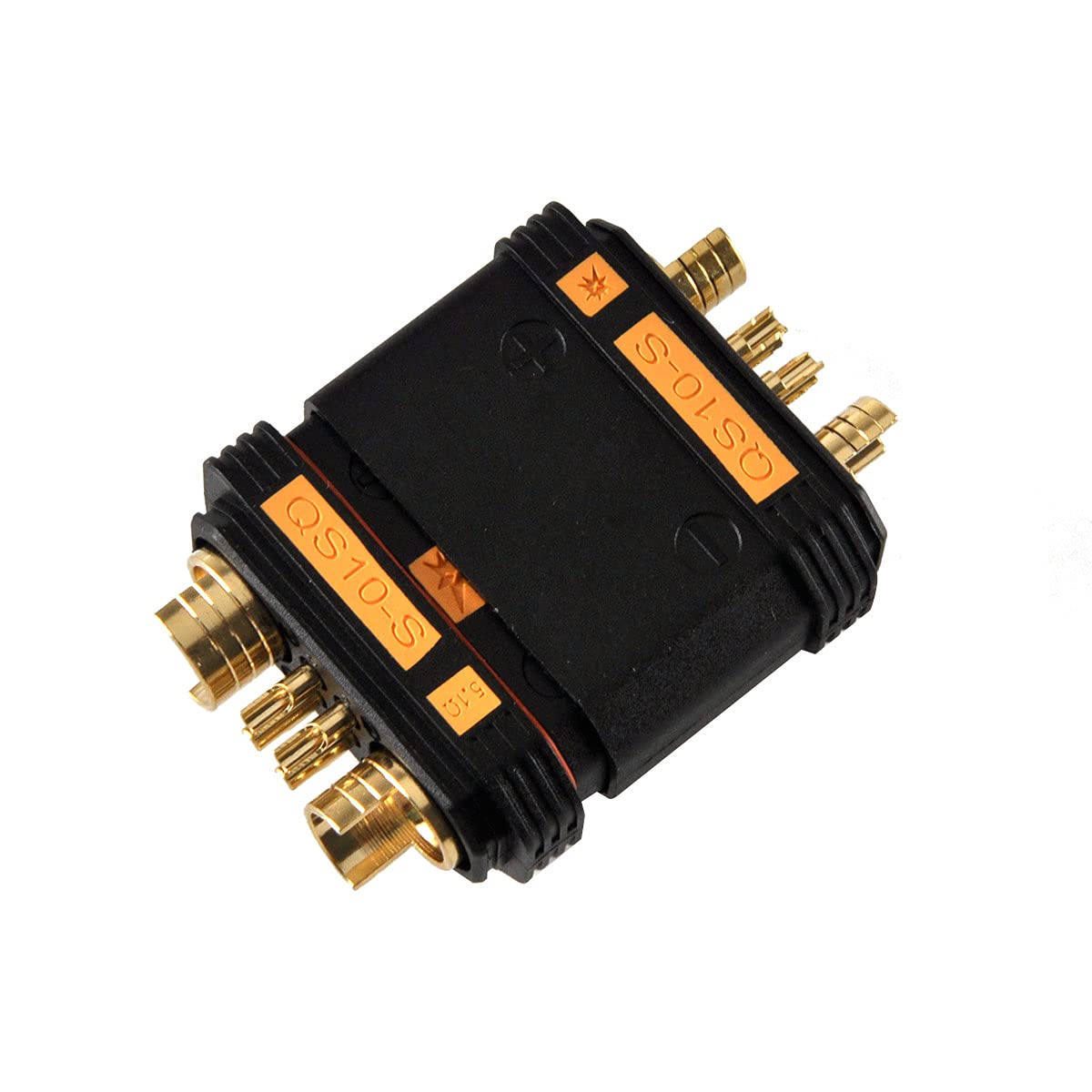
Image 2: Close-up view of the QS10-S male and female connectors, highlighting the gold-plated pins and the smaller anti-spark pin on the male connector.

Image 3: The QS10-S connectors partially disassembled, revealing the solder cups where wires are to be connected.
5. Operating Instructions
The QS10-S connectors are designed for easy and secure connection, with an integrated anti-spark feature.
- Connecting: Align the male and female connectors, ensuring the polarity markings match. Push the connectors firmly together until they click into place. The anti-spark pin on the male connector will make contact first, pre-charging capacitors and preventing a large spark.
- Disconnecting: Grip both connectors firmly and pull them apart. Avoid pulling on the wires, as this can damage the solder joints or the wires themselves.

Image 4: A pair of QS10-S connectors fully engaged, demonstrating a secure connection.

Image 5: The QS10-S connectors partially separated, showing the robust design and connection mechanism.
6. Maintenance
Regular inspection and proper care will extend the lifespan of your QS10-S connectors.
- Visual Inspection: Before each use, check the connectors for any signs of physical damage, such as cracks in the plastic housing, bent pins, or discoloration from overheating.
- Cleanliness: Keep the connector pins clean and free of dirt, dust, or corrosion. A clean, dry cloth can be used for light cleaning. Avoid using abrasive materials or harsh chemicals.
- Storage: Store connectors in a clean, dry environment away from extreme temperatures and direct sunlight.
7. Troubleshooting
This section addresses common issues you might encounter with your QS10-S connectors.
| Problem | Possible Cause | Solution |
|---|---|---|
| Difficulty connecting/disconnecting | Misalignment, new connectors (tight fit), dirt/debris. | Ensure correct alignment. New connectors may require more force initially. Clean pins if dirty. |
| Connector overheating | Poor solder joints, undersized wires, excessive current draw, damaged pins. | Inspect solder joints and re-solder if necessary. Use appropriate wire gauge. Verify current draw is within connector limits. Replace damaged connectors. |
| Sparking during connection (despite anti-spark feature) | Anti-spark pin not making contact first, damaged anti-spark pin, extremely high capacitance load. | Ensure connectors are pushed together straight. Inspect anti-spark pin for damage. While rare, some very high capacitance systems might still show a minimal spark. |
| Intermittent connection | Loose solder joints, corroded pins, bent pins, internal wire damage. | Check and re-solder connections. Clean pins. Straighten bent pins carefully or replace connector. Inspect wires for damage. |
8. Specifications
Technical specifications for the Flight Model QS10-S Anti-Spark Battery Connector.
- Model: QS10-S
- Current Rating: Up to 180A (continuous)
- Feature: Anti-Spark design
- Pin Material: Gold-plated copper
- Housing Material: High-temperature resistant plastic
- Recommended Wire Gauge: Up to 6AWG (for optimal performance at high currents)
- Manufacturer: Flight Model

Image 6: A single QS10-S connector, showing the robust construction and clear positive/negative polarity indicators.


