1. Introduction
The DALY Smart BMS (Battery Management System) is designed for LiFePo4 4S 12V battery packs, offering comprehensive protection and monitoring capabilities. This programmable BMS features a Bluetooth module for wireless communication with Android or iPhone applications, allowing users to manage and monitor battery status in real-time. It supports both charging and discharging through a common port, ensuring efficient and safe battery operation.
This manual provides detailed instructions for the proper installation, operation, and maintenance of your DALY Smart BMS to ensure optimal performance and longevity of your battery system.

Figure 1: DALY Smart BMS with Bluetooth Module and App Interface
2. Key Features
- High Current Capacity: Supports up to 250A continuous discharge and 125A charge current, suitable for demanding applications.
- Programmable Protections: Features adjustable over-charge, over-discharge, over-current, and temperature protection limits.
- Bluetooth Connectivity: Integrated Bluetooth module for real-time monitoring and parameter settings via mobile app (iOS & Android).
- Common Port Design: Utilizes a single port for both charging and discharging, simplifying wiring.
- Accurate SOC Calculation: Precise State of Charge (SOC) calculation with automatic learning function.
- Voltage Balancing: High detection precision for voltage balancing across cells.
- Low Temperature Charging Protection: Protects the battery from charging at temperatures below -1°C.
- Comprehensive Protection Functions: Includes protection against over-voltage, short-circuit, and dust.
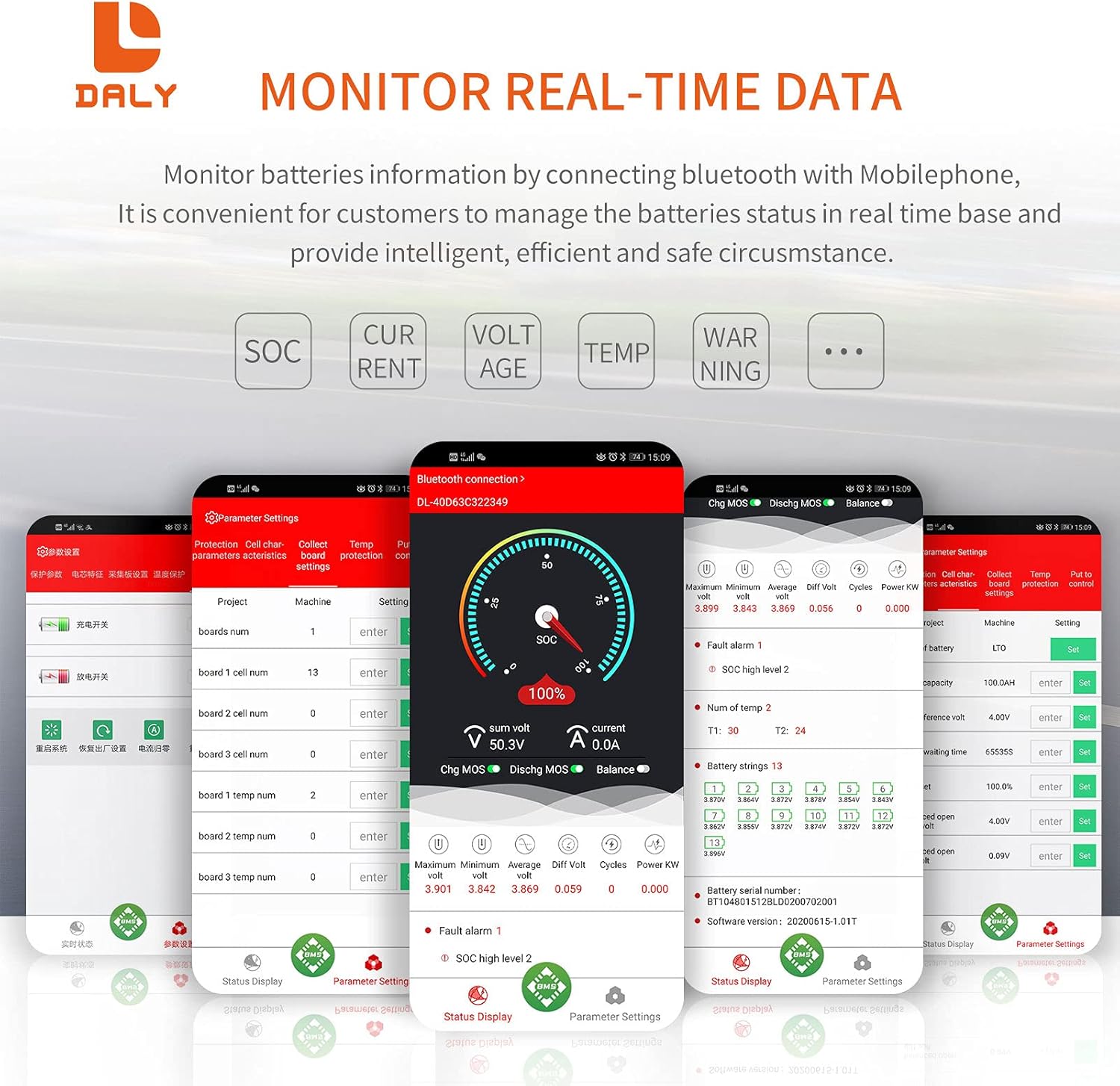
Figure 2: DALY Smart BMS Protection Functions
3. Package Contents
Verify that all items are present in the package before proceeding with installation:
- DALY Smart BMS (1 unit)
- Balance Wires (1 set)
- Bluetooth Module (1 unit, for Mobile APP IOS & Android)
- UART Cable (1 unit, for PC screen connection)
- English Version Wiring Manual (1 copy)

Figure 3: DALY Smart BMS Package Contents
4. Product Overview
The DALY Smart BMS features a robust design with efficient heat dissipation and a clear interface for connections. Understanding its components is crucial for proper installation and operation.
Figure 4: Exploded View of DALY Smart BMS Components
Key components include:
- Heatsinks: Two-wheels style and wave style heatsinks for effective thermal management.
- High Current Board: Designed with a 3mm thick pure copper port for high current applications.
- DALY BMS PCBA: The main printed circuit board assembly.
- Thermally Conductive Silica Gel: Enhances heat transfer.
- Pure Aluminum Heatsink: Additional heatsink for optimal cooling.
5. Setup and Installation
Proper installation is critical for the safe and effective operation of your DALY Smart BMS. Please follow these steps carefully.
5.1 Wiring Instructions
- Before connecting the BMS, ensure all balance wires are correctly welded to your battery pack.
- Measure the voltage between adjacent balance cables. This should approximate the nominal voltage of a single battery string to confirm correct wiring.
- Connect the balance wires to the BMS balance port. Ensure the black wire (B-) is connected first, followed by the red balance wires in ascending order.
- Connect the main negative terminal of the battery pack (B-) to the B- terminal on the BMS.
- Connect the main positive terminal of the battery pack (B+) to the P+ terminal on the BMS.
- Connect your load/charger to the P- terminal on the BMS and the B+ terminal of the battery pack.
- Plug in the NTC temperature sensor and the Bluetooth module into their respective ports on the BMS.
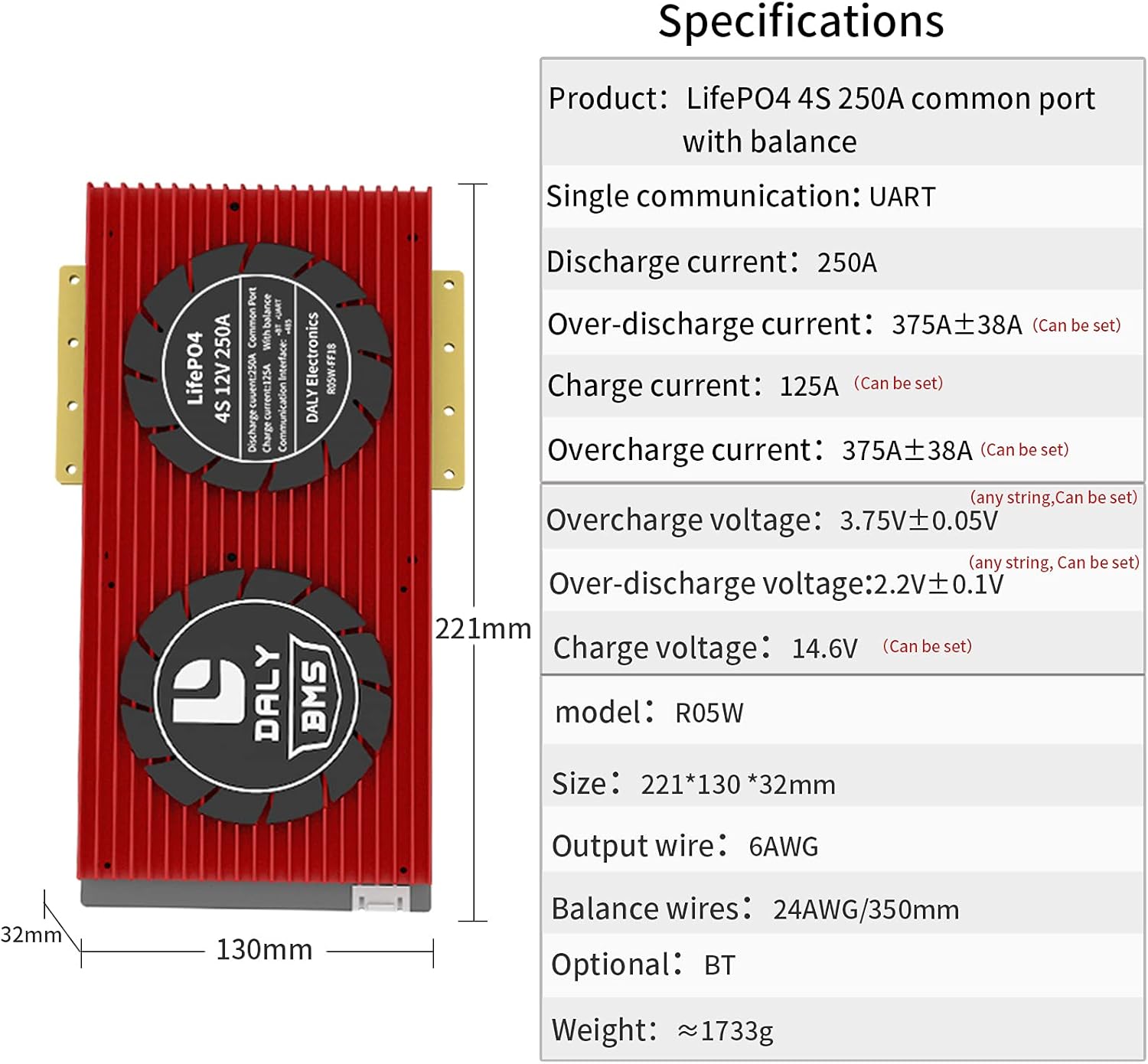
Figure 5: DALY Smart BMS Wiring Diagram
5.2 BMS Activation
After all connections are made, activate the Smart BMS by pressing the activation button on the BMS or by charging the battery pack. The internal resistance of the BMS should be approximately 0Ω (multimeter deviation 0.1Ω indicates conduction).
5.3 Mobile App Installation
Download the "Smart BMS" application from your device's app store (Huawei AppGallery or Apple App Store). This app allows you to monitor and configure your BMS wirelessly via Bluetooth.
Video 1: DALY Smart BMS Setup and App Overview. This video demonstrates the functional interfaces of the DALY Smart BMS, the cable connection process, activation steps, downloading and connecting to the Smart BMS mobile application, viewing battery parameters, adjusting settings, and using the PC host computer interface for comprehensive battery management.
6. Operation
Once installed and activated, you can operate and monitor your DALY Smart BMS using the mobile application or PC software.
6.1 Bluetooth Connection and Monitoring
- Open the "Smart BMS" app on your mobile device.
- The app will scan for available Bluetooth devices. Select the corresponding device name (e.g., DL-XXXXXXXX) to connect.
- Upon successful connection, the app will display real-time battery parameters such as total voltage, current, State of Charge (SOC), and individual cell voltages.

Figure 6: Real-time Battery Data Monitoring via Mobile App
6.2 Parameter Settings
The Smart BMS app allows you to customize various protection parameters. For the first power-on, it is essential to set the actual battery capacity. The initial password for parameter settings is 123456.
You can adjust settings such as:
- Cell over-voltage and under-voltage protection limits.
- Total pack over-voltage and under-voltage protection limits.
- Charge and discharge over-current protection.
- High and low temperature protection for charging and discharging.
- Battery type (e.g., Li-ion, LiFePo4) and rated capacity.
Refer to the app interface for a complete list of adjustable parameters. Always consult your battery manufacturer's specifications before modifying any parameters.
6.3 Automatic Calibration
The BMS features an automatic calibration function. If the battery is charged until the voltage reaches a high level 2 alarm, the battery parameters will be automatically calibrated.
6.4 PC Host Computer Software
For advanced monitoring and configuration, connect the BMS to a computer using the provided UART cable. Open the host computer software to view detailed battery status, logs, and adjust parameters. The PC software provides a comprehensive interface for in-depth analysis and control.
7. Specifications
The following table outlines the technical specifications for the DALY Smart BMS LiFePo4 4S 12V 250A model:
| Feature | Specification |
|---|---|
| Product Type | LiFePo4 4S 250A Smart BMS |
| Communication | UART (Bluetooth optional) |
| Discharge Current | 250A |
| Over-discharge Current | 375A ± 38A (Configurable) |
| Charge Current | 125A (Configurable) |
| Overcharge Current | 375A ± 38A (Configurable) |
| Overcharge Voltage | 3.75V ± 0.05V (per string, Configurable) |
| Over-discharge Voltage | 2.2V ± 0.1V (per string, Configurable) |
| Charge Voltage | 14.6V (Configurable) |
| Model | R05W |
| Dimensions | 221 * 130 * 32 mm |
| Output Wire | 6AWG |
| Balance Wires | 24AWG/350mm |
| Weight | ~1733g |

Figure 7: DALY Smart BMS Specifications and Dimensions
8. Troubleshooting
If you encounter issues with your DALY Smart BMS, consider the following general troubleshooting steps:
- No Power/No Output: Check all wiring connections for looseness or incorrect polarity. Ensure the BMS has been properly activated. Verify the battery pack voltage is within the operational range.
- Bluetooth Connection Issues: Ensure the Bluetooth module is securely connected to the BMS. Restart the mobile app and your device's Bluetooth. Confirm the BMS is powered on.
- Incorrect Readings: Double-check balance wire connections and ensure they are properly seated. If using the app, refresh the data.
- Over-Protection Triggered: If the BMS frequently triggers over-charge, over-discharge, or over-current protection, review your battery pack's specifications and adjust the BMS parameters accordingly. Ensure your load and charger are within the BMS's rated limits.
- Temperature Alarms: Verify the NTC temperature sensor is correctly installed and in contact with the battery cells. Ensure the battery is operating within its safe temperature range.
For persistent issues, refer to the detailed wiring manual included in your package or contact DALY customer support.
9. Maintenance
To ensure the longevity and optimal performance of your DALY Smart BMS and battery pack, follow these maintenance guidelines:
- Regular Inspection: Periodically inspect all wiring connections for signs of wear, corrosion, or looseness. Ensure the BMS is securely mounted.
- Cleanliness: Keep the BMS free from dust, dirt, and moisture. Use a dry, soft cloth for cleaning. Avoid using solvents or abrasive cleaners.
- Temperature Management: Ensure the BMS and battery pack are operated within their specified temperature ranges. Adequate ventilation is crucial to prevent overheating.
- Software Updates: Check for periodic updates to the Smart BMS mobile application or PC software to benefit from new features and bug fixes.
- Parameter Review: Occasionally review your BMS parameters to ensure they are still appropriate for your battery pack's condition and usage patterns.
10. Warranty and Support
DALY products are manufactured to high-quality standards. For warranty information, please refer to the documentation provided with your purchase or contact your retailer. Keep your proof of purchase for warranty claims.
For technical support, assistance with installation, or troubleshooting, please contact DALY customer service through their official website or the contact information provided in your product packaging. When contacting support, please have your product model number and purchase details ready.