1. Product Overview
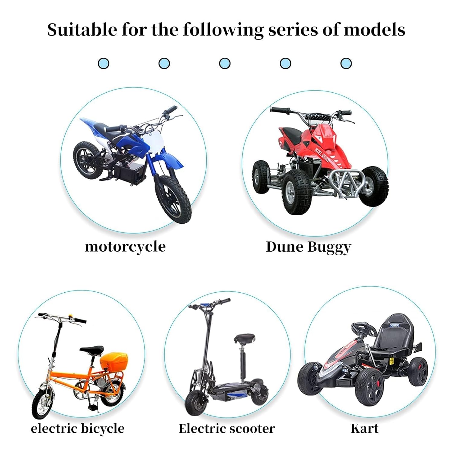
This manual provides essential information for the safe and efficient installation, operation, and maintenance of your Kunray 36V 1000W BLDC Mid Motor Kit. This kit is designed for various applications including Go Karts, E-bikes, Scooters, mini Motorcycles, and Quad ATVs.
Key Features:
- High-Speed Powerful Mid Motor: 36V 1000W Brushless DC Motor with a rated speed of 3100 RPM and a rated current of 27.7A.
- Efficient Design: Compact and lightweight aluminum shell for improved power efficiency and durability. Features a wind-cold hole for heat dissipation.
- Positive & Negative Rotation: Motor direction can be controlled via a reversing wire or handlebar reverse switch.
- 3-Speed Functionality: Offers Low (50%), Mid (70-80%), and High (100%) speed settings.
- 12-Mosfet 30A Brushless Motor Controller: High-quality controller with Hall 3-speed, reverse throttle, charging, e-braking, power lock, and light functions.
2. Safety Information
Please read all safety warnings and instructions carefully before installation and operation to prevent injury or damage to the product.
- Burn Hazard: Do not touch the motor with your body during use, as it can become hot and cause burns.
- Installation: Ensure all connections are secure and correctly wired according to the instructions to avoid electrical shock or damage.
- Off-Road Use: Kunray motors are designed for off-road use only. Always check and comply with local laws and regulations regarding electric vehicle use.
- Traffic Safety: Always yield to pedestrians and obey traffic regulations. Be aware that riding on sidewalks may be prohibited in your area.
- Not a Toy: This device is not a toy. Keep it away from children.
- Electrical Safety: Disconnect power before performing any maintenance or installation. Avoid exposing electrical components to water or extreme moisture.
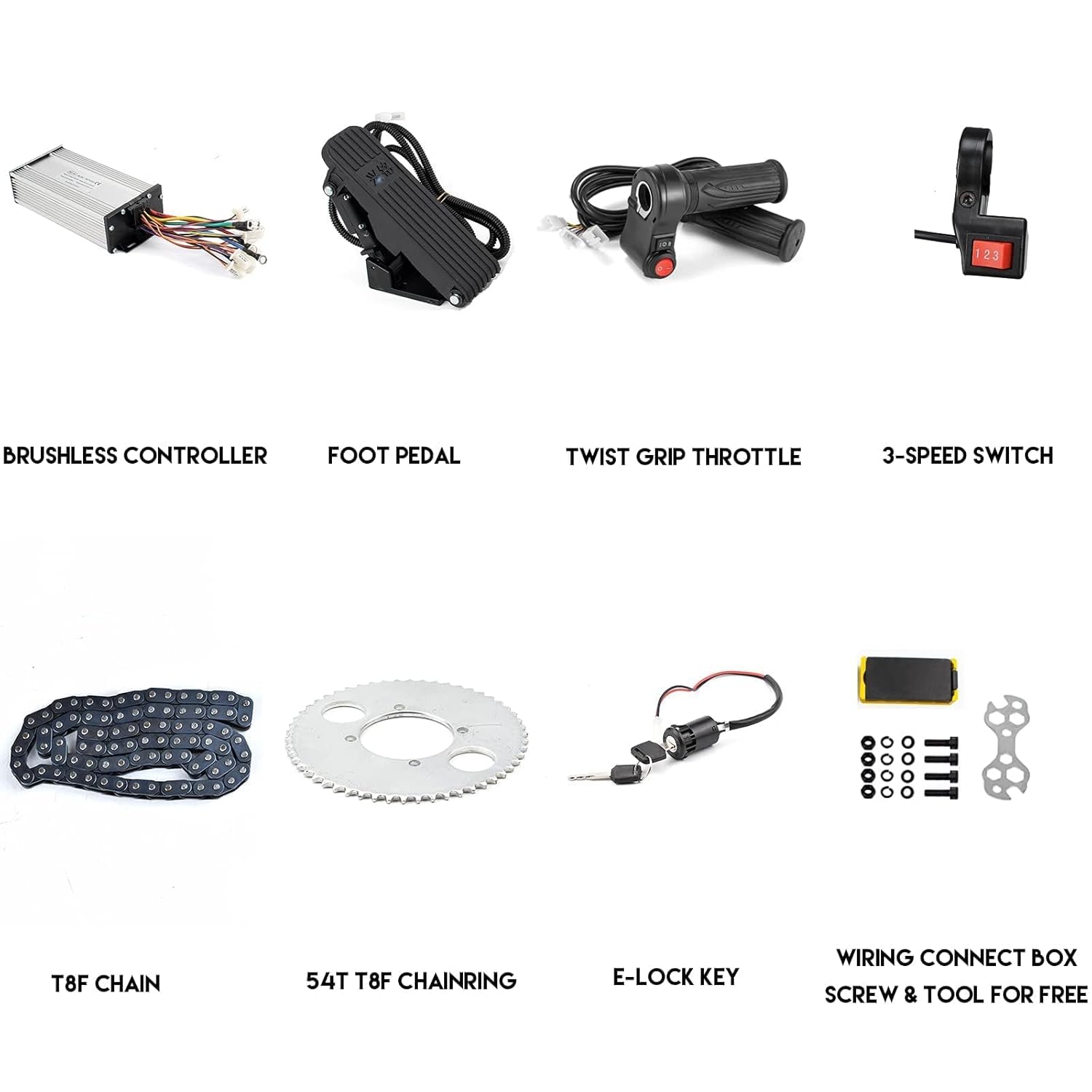
3. What's in the Box
The Kunray 36V 1000W BLDC Mid Motor Kit includes the following components:
- 1000W BLDC Motor
- Speed Controller (12MOS 30A)
- Handlebar Twist Grip Throttle
- Foot Throttle
- Power Lock Key
- T8F Tooth Plate Ring (Sprocket)
- T8F Chain
- 3-Speed Switch
- Wiring Connect Box, Screws & Tools (for free)


4. Setup and Installation
Careful installation is crucial for optimal performance and safety. It is recommended to have basic electrical and mechanical knowledge or seek professional assistance.
4.1 Motor Mounting
- Identify a suitable mounting location on your vehicle (Go Kart, E-bike, etc.) that allows for proper chain alignment and clearance.
- Secure the motor using its integrated mounting bracket. Ensure it is firmly attached to prevent movement during operation.
- Install the T8F Tooth Plate Ring (sprocket) onto the motor shaft.
- Align the T8F chain between the motor sprocket and the vehicle's drive sprocket. Adjust tension as needed.


4.2 Wiring Connections
Refer to the wiring diagram below for correct connections. Ensure all connections are tight and insulated.
- Battery Connection: Connect the battery positive (+) and negative (-) terminals to the corresponding wires on the controller.
- Motor Phase Wires: Connect the three motor phase wires (typically yellow, green, blue) from the motor to the controller.
- Hall Sensor Wires: Connect the Hall sensor wires from the motor to the controller.
- Electric Lock: Connect the electric lock wires to the power lock key.
- Charging Port: Connect the charging port if applicable.
- Reversing Wire: Connect the reversing wire or switch if reverse functionality is desired.
- 3-Speed Switch: Connect the 3-speed switch wires.
- Brake Light & Brakes: Connect brake light and brake lever wires.
- Throttle: Connect the twist grip or foot pedal throttle.
- Indicator Light: Connect the indicator light if included.

5. Operating Instructions
5.1 Power On/Off
Insert the key into the power lock and turn it to the 'ON' position to power on the system. Turn the key to 'OFF' to power off.
5.2 Speed Control
The kit includes both a handlebar twist grip throttle and a foot pedal throttle. Use the one appropriate for your application.

- Throttle Operation: Gently apply the throttle to accelerate. Release the throttle to decelerate.
- 3-Speed Switch: Use the 3-speed switch to select between Low (50% power), Mid (70-80% power), and High (100% power) settings.
5.3 Direction Control (Forward/Reverse)
The BLDC motor supports both positive (forward) and negative (reverse) rotation. This can be controlled via a dedicated reversing wire connected to the controller or a switch on the handlebar throttle.
- Caution: Do not operate the motor in reverse for extended periods, as this is not recommended for motor longevity and safety.
5.4 Braking
Engage the brake levers to activate the e-braking function and mechanical brakes (if installed). Ensure brakes are functioning correctly before operation.
6. Maintenance
Regular maintenance ensures the longevity and safe operation of your motor kit.
- Regular Inspection: Periodically check all electrical connections for tightness and signs of wear or corrosion.
- Motor & Controller: Keep the motor and controller clean and free from dirt, dust, and debris. Ensure the heatsink fins are clear for optimal cooling.
- Chain & Sprocket: Inspect the chain and sprockets for wear. Lubricate the chain regularly to reduce friction and extend its life.
- Wiring: Check all wiring for fraying, cuts, or damage. Replace any damaged wires immediately.
- Battery: Follow the battery manufacturer's guidelines for charging and maintenance.
7. Troubleshooting
This section addresses common issues you might encounter. For problems not listed here, please contact customer support.
| Problem | Possible Cause | Solution |
|---|---|---|
| Motor does not run or has low power. |
|
|
| Motor runs in the wrong direction. |
|
|
| Sprocket or chain issues (e.g., chain coming off). |
|
|
| No response from throttle. |
|
|
8. Product Specifications
| Specification | Value |
|---|---|
| Brand | Kunray |
| Model Number | 36-1000 |
| Voltage | 36 Volts |
| Horsepower / Power Output | 1000 Watts |
| Rated Speed (No-load) | 3100 RPM |
| Motor Rated Current | 27.7A |
| Controller Type | 12Mosfet 30A Brushless Motor Controller |
| Material | Aluminum |
| Motor Weight | Approximately 3.3 kg (7.3 lb) |
| Motor Wiring Length | Approximately 150 cm (59 inch) |
| Package Dimensions | 14 x 12.1 x 8.4 inches |
9. Warranty Information
For detailed warranty information regarding your Kunray 36V 1000W BLDC Mid Motor Kit, please refer to the seller or manufacturer's official website. Warranty terms and conditions may vary based on purchase location and specific product policies.
10. Customer Support
If you encounter any issues or have questions not covered in this manual, please contact the seller or manufacturer directly for assistance. Provide your product model number (36-1000) and a detailed description of the issue to facilitate support.