1. Introduction
The SATMW UT89XE is a professional digital multimeter designed for accurate and reliable electrical measurements. It features a 20000-count true RMS display, high resolution, and a comprehensive range of functions including DC/AC voltage, current, resistance, capacitance, temperature, and a unique conductivity measurement function. This device is engineered to meet CAT II 1000V/CAT III 600V safety standards, incorporating over-voltage and over-current protection for user safety.
2. Safety Information
To ensure safe operation and prevent damage to the meter, please read and follow all safety instructions carefully. This device complies with CAT II 1000V and CAT III 600V safety ratings.
- Always observe local and national safety codes.
- Use appropriate personal protective equipment (PPE), such as safety glasses and insulated gloves, when working with electrical circuits.
- Do not exceed the maximum input limits specified for each range.
- Ensure test leads are in good condition, free from cracks or damage, and properly connected to the meter and the circuit under test.
- Do not use the multimeter if it appears damaged or is not operating correctly.
- Be extremely cautious when working with live circuits. Avoid contact with bare wires or terminals.
- Replace batteries and fuses only with the specified type and rating.
- Disconnect test leads from the circuit before changing functions or ranges.
- Avoid using the meter in wet environments or in the presence of explosive gases or dust.
3. Product Overview
The UT89XE Digital Multimeter is designed for versatility and precision. Key features include:
- True RMS Measurement: Provides accurate readings for non-sinusoidal waveforms.
- High Resolution: 20000 display counts for precise measurements.
- Wide Measurement Ranges: Up to 1000V AC/DC voltage, 20A AC/DC current, 200MΩ resistance, 200000uF capacitance.
- Conductivity Measurement: Unique function (0.1-200nS) for measuring large resistances (5Ω-10GΩ).
- Low Pass Filter (LPF): Essential for accurate voltage and frequency measurements on variable frequency drives.
- Temperature Measurement: Range from -10℃ to 1000℃ (-40℉ to 1832℉).
- Safety Features: Over-voltage and over-current alarm prompts, high-voltage misdetection protection.
- Ergonomic Design: Double injection molding for durability and a comfortable grip, with 1-meter anti-falling reliability.
- Convenience: Auto backlight, auto power off, data hold, MAX/MIN, Peak value/Relative value functions.

Figure 3.1: Front view of the SATMW UT89XE Digital Multimeter, showing the display, rotary switch, and input jacks.

Figure 3.2: Overview of the UT89XE's key features and design.
4. Setup
4.1 Battery Installation
The UT89XE typically uses AA batteries (quantity may vary, refer to the battery compartment cover). To install or replace batteries:
- Ensure the multimeter is powered off and disconnect all test leads from the input terminals.
- Locate the battery compartment cover on the back of the meter.
- Use a screwdriver to loosen the screw(s) securing the cover.
- Remove the cover and insert new batteries, observing the correct polarity (+ and -).
- Replace the battery compartment cover and tighten the screw(s).
4.2 Connecting Test Leads
Proper connection of test leads is crucial for accurate and safe measurements.
- Insert the black test lead into the COM (common) input jack.
- For most voltage, resistance, capacitance, frequency, temperature, and diode/continuity measurements, insert the red test lead into the VΩHzT°C input jack.
- For current measurements up to 20A, insert the red test lead into the 20A input jack.
- For current measurements up to 200mA, insert the red test lead into the mAμA input jack.
Always ensure the test leads are securely inserted before taking any measurements.
5. Operating Instructions
The UT89XE uses a rotary switch to select the primary measurement function and function buttons for secondary options or special features.
5.1 Power On/Off
Rotate the central switch from the OFF position to any desired measurement function to power on the meter. To power off, rotate the switch back to the OFF position.
5.2 Function Buttons
- SELECT: Toggles between different measurement types within a single rotary switch position (e.g., AC/DC voltage, diode/continuity).
- HOLD: Freezes the current reading on the display. Press again to release.
- MAX/MIN: Displays the maximum or minimum reading recorded since the function was activated. Press repeatedly to cycle through MAX, MIN, and current reading.
- REL (Relative Mode): Stores the current reading as a reference value and displays subsequent measurements as a deviation from this reference.
5.3 Measurement Functions
Select the desired function using the rotary switch. Use the SELECT button to switch between AC/DC or other sub-functions if applicable.
5.3.1 DC/AC Voltage Measurement (V= / V~)
- Set the rotary switch to the V position.
- Use the SELECT button to choose between DC (V=) or AC (V~).
- Connect the red test lead to the VΩHzT°C jack and the black test lead to the COM jack.
- Connect the test probes in parallel across the component or circuit to be measured.
5.3.2 DC/AC Current Measurement (A= / A~)
- Set the rotary switch to the A (for 20A) or mAμA position.
- Use the SELECT button to choose between DC (A=) or AC (A~).
- Connect the black test lead to the COM jack.
- Connect the red test lead to the 20A jack for high current or mAμA jack for low current.
- Important: Connect the meter in series with the circuit. Ensure the circuit is de-energized before connecting the meter.
5.3.3 Resistance Measurement (Ω)
- Set the rotary switch to the Ω position.
- Connect the red test lead to the VΩHzT°C jack and the black test lead to the COM jack.
- Ensure the circuit or component is de-energized before connecting the probes across the resistance to be measured.
5.3.4 Capacitance Measurement (F)
- Set the rotary switch to the F position.
- Connect the red test lead to the VΩHzT°C jack and the black test lead to the COM jack.
- Important: Discharge capacitors completely before measuring to prevent damage to the meter or injury. Connect the probes across the capacitor terminals.
5.3.5 Temperature Measurement (°C/°F)
- Set the rotary switch to the °C/°F position.
- Connect the temperature probe (K-type thermocouple, not always included) to the appropriate input jacks, observing polarity.
- Place the tip of the temperature probe on or near the object whose temperature is to be measured.
5.3.6 Conductance Measurement (nS)
The UT89XE features a conductance measurement function, which is useful for measuring very high resistances that are beyond the typical resistance range of multimeters.
- Set the rotary switch to the nS position.
- Connect the red test lead to the VΩHzT°C jack and the black test lead to the COM jack.
- Connect the probes across the component. The reading will be in nanoSiemens (nS).
- To convert conductance (G) to resistance (R), use the formula R = 1/G. For example, 1 nS = 1 / (1 x 10⁻⁹ S) = 1 x 10⁹ Ω = 1 GΩ.
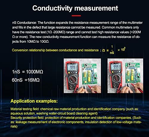
Figure 5.1: Detailed explanation of the conductivity measurement function and its application.
5.3.7 Frequency Measurement (Hz)
- Set the rotary switch to the Hz position.
- Connect the red test lead to the VΩHzT°C jack and the black test lead to the COM jack.
- Connect the probes across the signal source to measure its frequency.
5.3.8 Diode Test (->|) and Continuity Test (Buzzer)
- Set the rotary switch to the Diode/Continuity position.
- Use the SELECT button to toggle between Diode Test and Continuity Test.
- For Diode Test: Connect the red probe to the anode and the black probe to the cathode. The display shows the forward voltage drop. Reverse the probes; the display should show OL (open loop).
- For Continuity Test: Connect the probes across the circuit. An audible beep indicates continuity (low resistance).
5.3.9 Low Pass Filter (LPF)
The LPF function is designed to accurately measure voltage and frequency on variable frequency drives (VFDs) and other noisy electrical equipment. It filters out high-frequency noise components, allowing for a more stable and accurate reading of the fundamental frequency and voltage.
- Select the AC Voltage (V~) or Frequency (Hz) function.
- Press the LPF button (if available, or a combination of SELECT/function button as per specific model).
- The LPF icon will appear on the display, indicating the filter is active.
- Proceed with your measurement as usual.
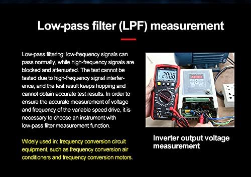
Figure 5.2: Description of the Low Pass Filter (LPF) function and its application in measuring inverter output voltage.
5.4 Application Scenarios

Figure 5.3: Examples of the UT89XE in use for various electrical and electronic testing applications.
6. Maintenance
Proper maintenance ensures the longevity and accuracy of your UT89XE Digital Multimeter.
6.1 Cleaning
Wipe the case with a damp cloth and mild detergent. Do not use abrasives or solvents. Ensure the meter is completely dry before use.
6.2 Battery Replacement
When the battery indicator appears on the display, replace the batteries as described in Section 4.1. Always use fresh batteries of the specified type.
6.3 Fuse Replacement
If the current measurement functions stop working, the fuse(s) may need replacement. Refer to the battery compartment or internal labels for fuse specifications. To replace a fuse:
- Ensure the meter is powered off and all test leads are disconnected.
- Open the battery compartment cover (and potentially the main back cover, depending on design).
- Carefully remove the old fuse(s).
- Install new fuse(s) of the exact same type and rating. Using incorrect fuses can damage the meter or compromise safety.
- Reassemble the meter securely.
6.4 Test Lead Care
Inspect test leads regularly for any signs of damage, such as cracked insulation or exposed wires. Replace damaged leads immediately to prevent electric shock hazards.
7. Troubleshooting
If your UT89XE multimeter is not functioning as expected, refer to the following common issues and solutions:
| Problem | Possible Cause | Solution |
|---|---|---|
| Meter does not power on. | Dead or incorrectly installed batteries. | Replace batteries, ensuring correct polarity. |
| No reading or "OL" displayed (except for diode reverse bias). | Open circuit; incorrect range; damaged test leads. | Check circuit continuity; select appropriate range; inspect and replace test leads. |
| Inaccurate readings. | Incorrect function selected; poor test lead contact; external interference. | Verify function and range; ensure good contact; move away from strong electromagnetic fields. |
| Current measurement not working. | Blown fuse; incorrect input jack. | Check and replace fuse (Section 6.3); ensure red lead is in the correct A or mAμA jack. |
| Display shows "Lo Batt". | Low battery power. | Replace batteries immediately. |
8. Specifications
The following table outlines the general specifications for the SATMW UT89XE Digital Multimeter.
| Feature | Specification |
|---|---|
| Display Count | 20000 |
| True RMS | Yes |
| Safety Rating | CAT II 1000V / CAT III 600V |
| DC Voltage Measurement | Up to 1000V |
| AC Voltage Measurement | Up to 1000V (45~1000Hz) |
| DC Current Measurement | Up to 20A |
| AC Current Measurement | Up to 20A |
| Resistance Measurement | Up to 200MΩ |
| Capacitance Measurement | Up to 200000uF |
| Temperature Measurement | -10℃ to 1000℃ / -40℉ to 1832℉ |
| Conductance Measurement | 0.1-200nS |
| Low Pass Filter (LPF) | Yes |
| Sampling Rate | 3 times/s |
| Special Functions | Peak value/Relative value, MAX/MIN, Data hold, Auto backlight, Auto power off, Audible/visual alarm |
| Power Source | Manual (Battery operated) |
| Anti-falling Reliability | 1 meter |
9. Warranty & Support
SATMW products are manufactured to high-quality standards. For specific warranty terms and conditions, please refer to the warranty card included with your product or contact your point of purchase. For technical support, troubleshooting assistance, or service inquiries, please contact SATMW customer service through the official website or your retailer.